
Daylighting fabric and method of making the same

a daylight fabric and fabric technology, applied in the field of natural lighting, can solve the problems of extending the area of the slit, and achieve the effect of minimizing the surface roughness of the slit and high edge quality

Active Publication Date: 2014-09-02
S V V TECH INNOVATIONS
View PDF36 Cites 16 Cited by
  • Summary
  • Abstract
  • Description
  • Claims
  • Application Information

AI Technical Summary

Benefits of technology

The patent describes a device with slits that spread a beam of light evenly across a flexible sheet. The device also uses a high-quality blade to minimize any roughness on the surface of the slits. This technology helps to create a more precise and controlled beam of light, which is useful in a variety of applications.

Problems solved by technology

Such stretching results in the elongation of sheet material in the areas of the slits.

Method used


Image

  • Daylighting fabric and method of making the same
  • Daylighting fabric and method of making the same
  • Daylighting fabric and method of making the same

Examples


example 1

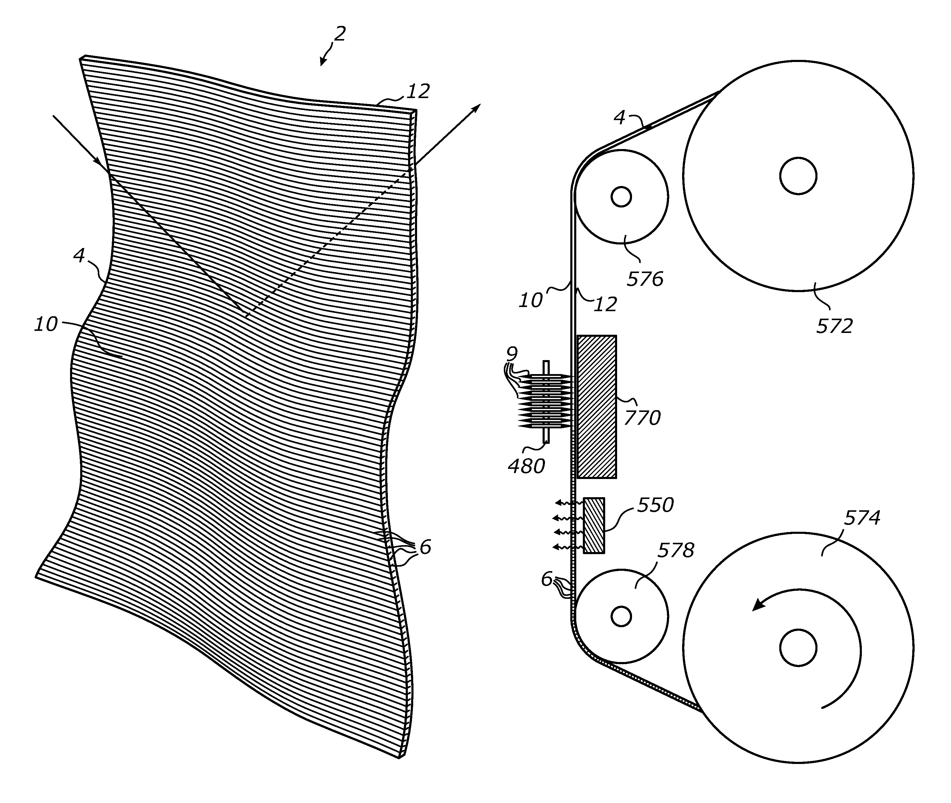
[0242]A rectangular sheet of 40-gauge (around 1 mm-thick) clear flexible vinyl (PVC) was formed into a loop and elastically stretched between two spaced apart, parallel rollers at a constant tension. A straight-edge rotary blade made from tungsten tool steel and manufactured by OLFA was used to produce an array of parallel slits in the flexible PVC sheet. The blade had the diameter of 28 mm and the thickness of around 0.3 mm (OLFA product number RB28). The blade was positioned perpendicular to the stretch direction on a linear guiding rail system and the slitting action was performed by a reciprocal movement of the blade through the entire width of the vinyl sheet using a linear actuator. The feed of the flexible vinyl sheet was performed by rotating the feed roller in small angular increments using a stepped drive coupled to the roller's axis. The depth of blade penetration into the sheet material was 0.75 mm which produced linear slits with nearly vertical walls and the depth of a...

example 2

[0246]A rectangular sheet of 40-gauge clear flexible vinyl was prepared and processed in much the same manner as in Example 1 except that another cutting blade was used. The new blade was a 28-mm rotary tungsten steel / carbon steel blade manufactured by Kai Industries (part #C-280BL). Such blades yielded the RMS surface profile roughness parameter Rq in the range between 0.012 μm (12 nm) and 0.025 μm (25 nm), corresponding to the calculated specular TIR reflectivity of the slit surfaces of at least 85% for the entire targeted range of incidence angles θi (from 49° to 90°). When exposed to direct sunlight, the processed sheet has produced a similar bright spot on the ceiling by redirecting the respective beam form the original propagation direction.

[0247]FIG. 15 depicts an exemplary surface profile measured for a wall of one of the slits made in Example 2 above. The X coordinate shows a local linear coordinate on the surface of the slit wall measured along the perpendicular to the lon...


PUM

PropertyMeasurementUnit
surface roughnessaaaaaaaaaa
thicknessaaaaaaaaaa

Abstract

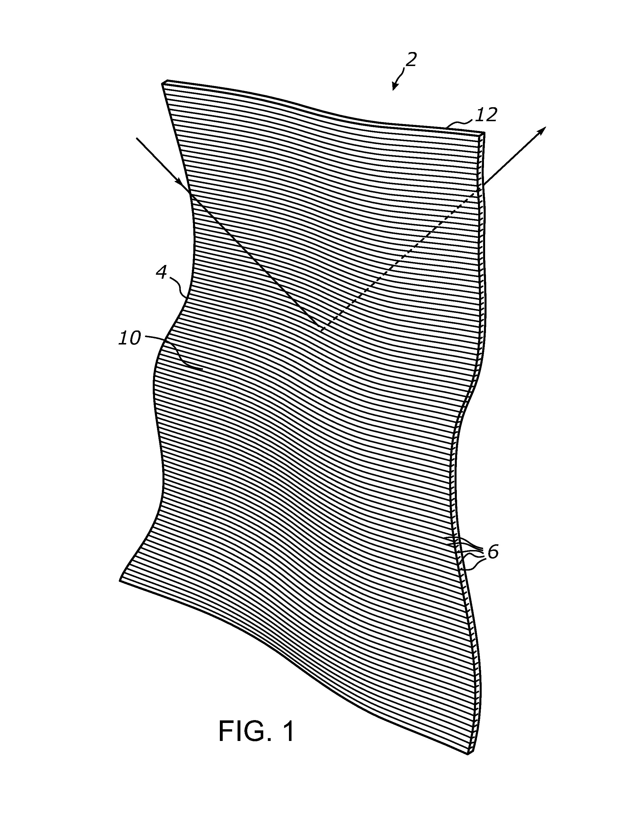
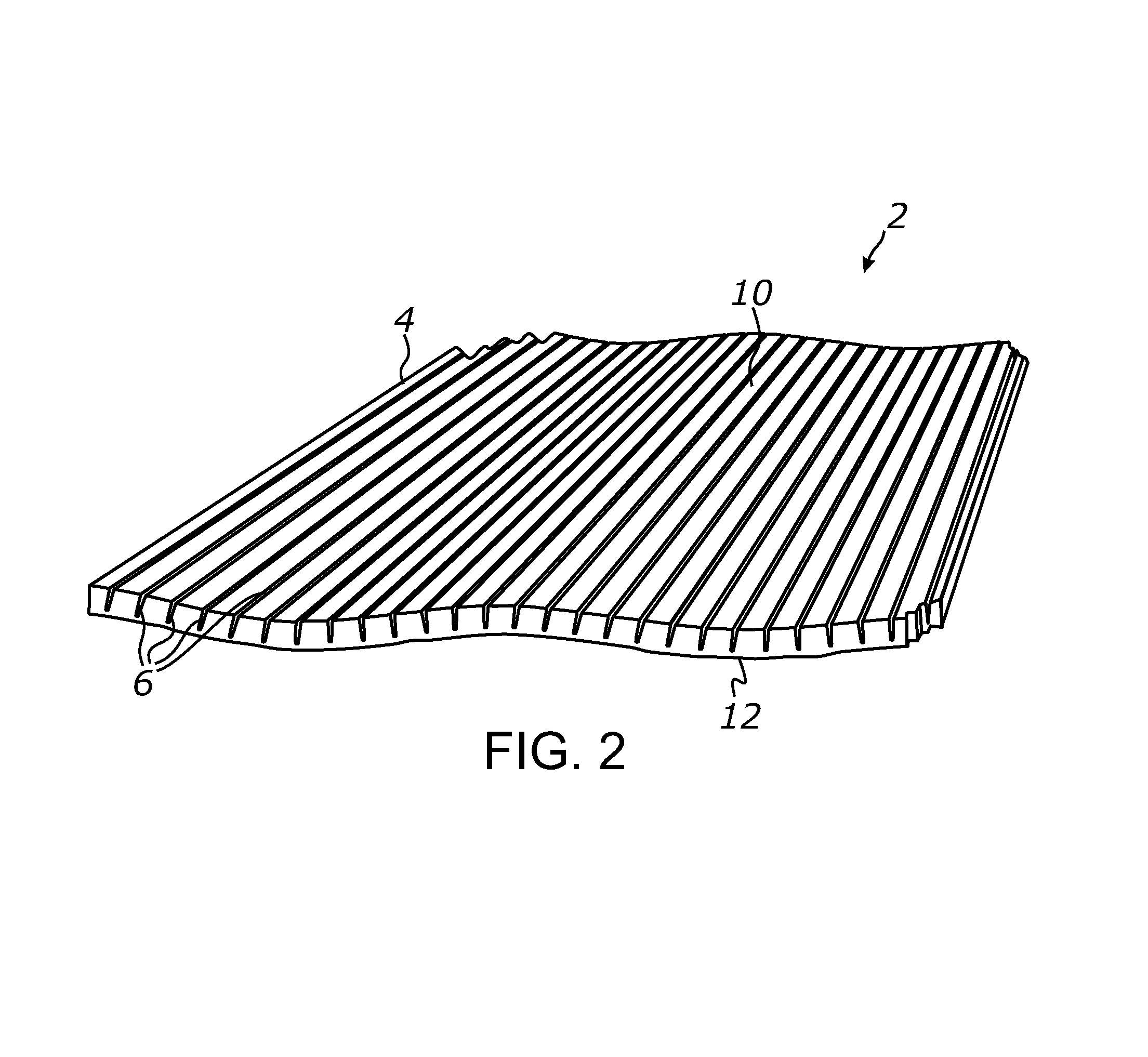
A flexible sheet-form optical system, referenced to as a daylighting fabric, which has a fabric-like behavior and light redirecting properties. The daylighting fabric comprises a soft and flexible sheet of optically transmissive material, such as plasticized polyvinyl chloride. A surface of the flexible sheet includes a plurality of parallel slits having spaced-apart walls configured to reflect light by means of a total internal reflection. At least a portion of daylight incident onto the sheet is internally redirected at angles other than the angle of incidence which is exploited to enhance daylight harvesting and illumination of a building interior. Disclosed also are a method and apparatus for making the daylighting fabric. The method includes steps of mechanical slitting of the flexible sheet with a blade, elastic stretch-elongation of the sheet along a direction perpendicular to the slits, and making at least a portion of the sheet elongation irreversible.

Description

CROSS-REFERENCE TO RELATED APPLICATIONS[0001]This application claims priority from U.S. provisional application Ser. No. 61 / 621,332 filed on Apr. 6, 2012, incorporated herein by reference in its entirety, U.S. provisional application Ser. No. 61 / 691,264 filed on Aug. 21, 2012, incorporated herein by reference in its entirety, and U.S. provisional application Ser. No. 61 / 775,678 filed on Mar. 10, 2013, incorporated herein by reference in its entirety.STATEMENT REGARDING FEDERALLY SPONSORED RESEARCH OR DEVELOPMENT[0002]Not ApplicableINCORPORATION-BY-REFERENCE OF MATERIAL SUBMITTED ON A COMPACT DISC[0003]Not ApplicableNOTICE OF MATERIAL SUBJECT TO COPYRIGHT PROTECTION[0004]A portion of the material in this patent document is subject to copyright protection under the copyright laws of the United States and of other countries. The owner of the copyright rights has no objection to the facsimile reproduction by anyone of the patent document or the patent disclosure, as it appears in the Un...

Claims


Application Information

Patent Timeline
Patent Type & Authority Patents(United States)
IPC IPC(8): G02B17/00F21S11/00B29D11/00G02B19/00
CPCG02B19/0042B29D11/00605F21S11/00B29D11/00663G02B19/0038G02B19/0028F21S11/007B29D11/0074E06B9/24
Inventor VASYLYEV, SERGIY
Owner S V V TECH INNOVATIONS
Learn More