
Coating method

a coating method and coating technology, applied in the direction of superimposed coating process, liquid/solution decomposition chemical coating, manufacturing tools, etc., can solve the problems of unobtainable color shade, unfavorable color development, appearance quality, etc., and achieve the effect of increasing the metallic effect of the coating film and high the flying velocity of the paint particles

Active Publication Date: 2014-09-09
NISSAN MOTOR CO LTD
View PDF18 Cites 0 Cited by
  • Summary
  • Abstract
  • Description
  • Claims
  • Application Information

AI Technical Summary

Benefits of technology

The present invention aims to provide a coating method that can create a desired color shade for various spray widths, while reducing the loss of paint and quickly determining a new coating condition. This is achieved by changing the spray pattern size of the paint particles, which in turn changes the flying velocity and impact velocity of the particles towards the surface of the object to be coated, leading to increased orientation of glitter pigment in parallel with the surface. By controlling these factors, the metallic effect of the coating film is increased. Additionally, the invention also addresses the issue of increased overspray when spray pattern size changes are limited.

Problems solved by technology

For this reason, the orientation of the glitter pigment contained in the paint changes, thus causing an uneven color development.
This results in a problem with appearance quality where a desired color shade cannot be obtained.
This brings about a problem with lead-time where a large amount of time for this study is required until a new paint color is employed.

Method used


Image

  • Coating method
  • Coating method
  • Coating method

Examples


Embodiment Construction

[0022]An embodiment of the present invention will be described in detail below with reference to the drawings.

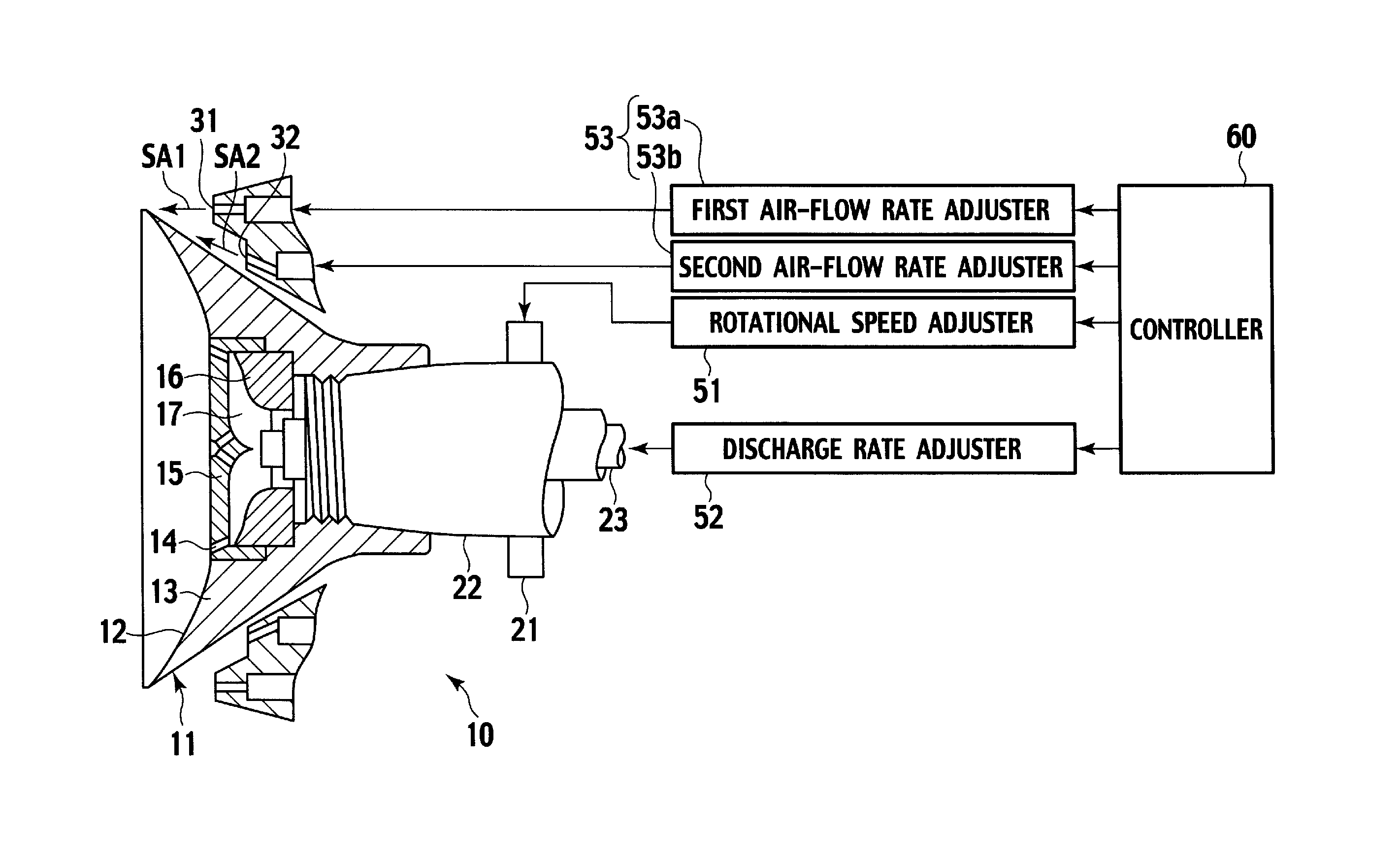
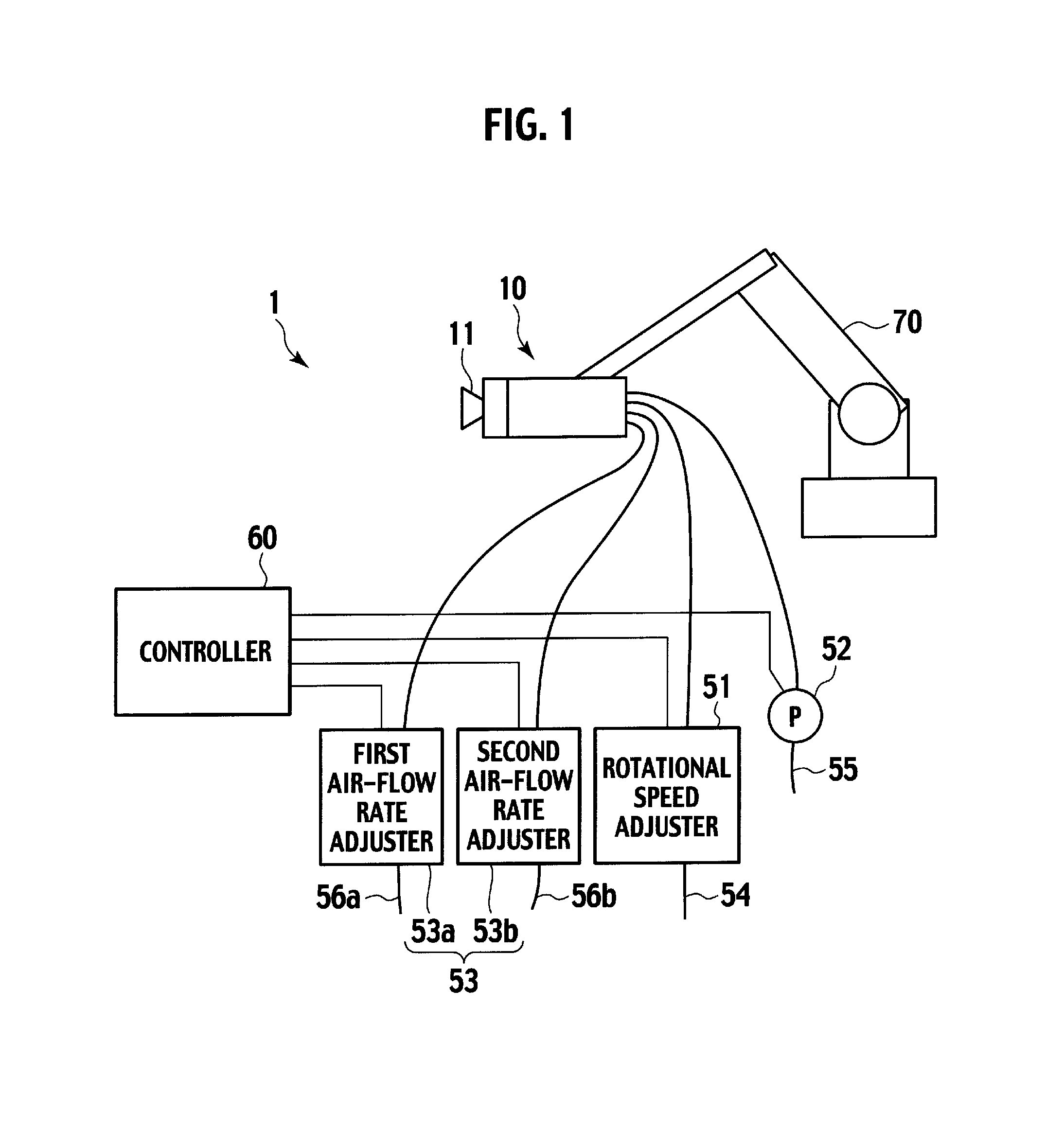
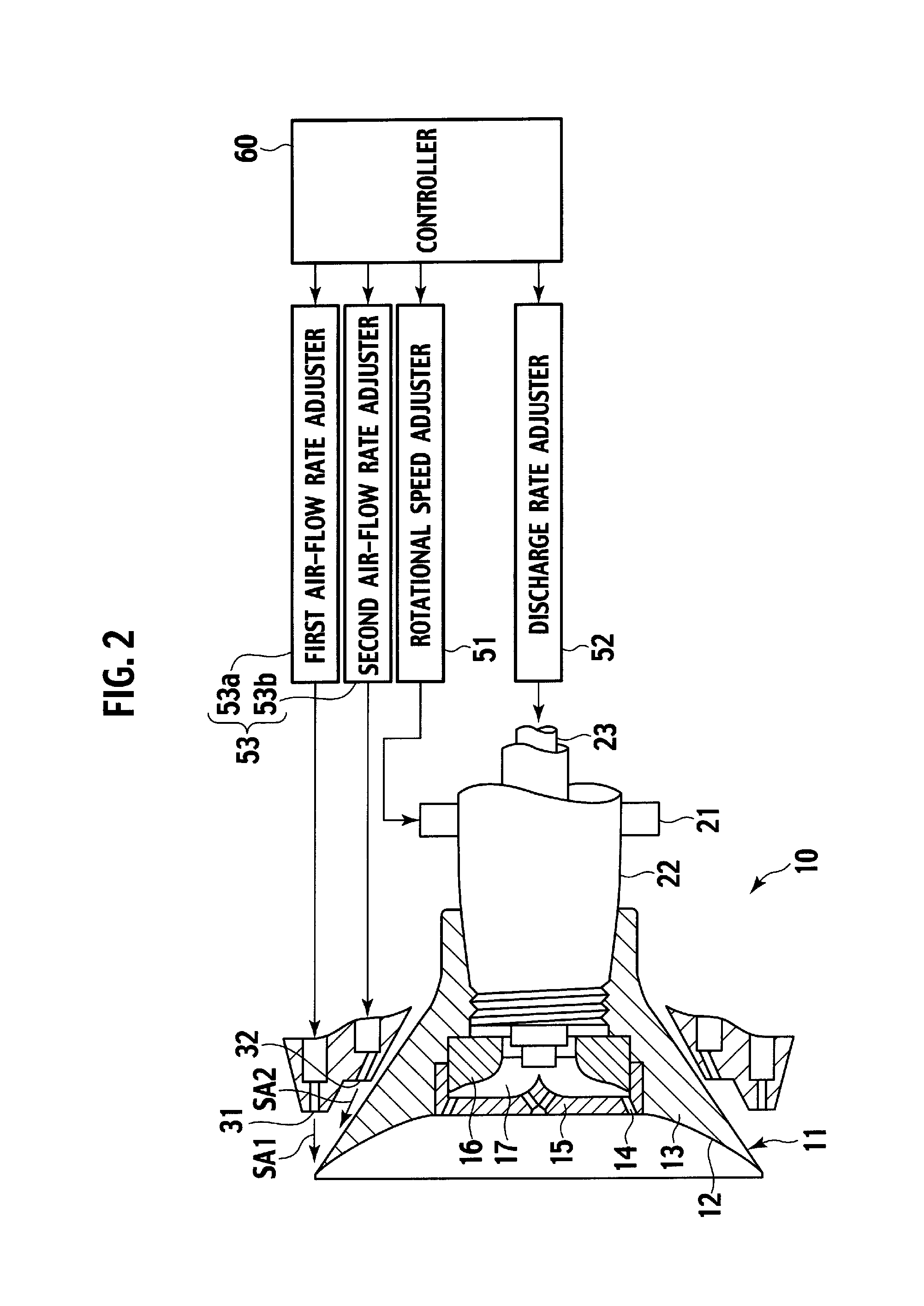
[0023]FIG. 1 is an overall structural view showing an outline of a coating apparatus according to the embodiment of the present invention. FIG. 2 is a view showing a rotary atomizer shown in FIG. 1 and its control structure.

[0024]A coating apparatus 1 of this embodiment coats a surface of an object to be coated, such as a body of an automobile, with paint containing a glitter pigment by spraying the paint on the surface.

[0025]As shown in FIG. 1, the coating apparatus 1 includes: a rotary atomizer 10 having a bell cup 11; a rotational speed adjuster 51 which adjusts the rotational speed of the bell cup 11; a discharge rate adjuster 52 which adjusts the discharge rate of paint; airflow rate adjusters 53 which adjust the airflow rate of shaping air to be blown from the rear side of the bell cup 11; and a controller 60 which adjusts the color shade of paint to be applied on the ...


PUM

PropertyMeasurementUnit
particle sizeaaaaaaaaaa
widthaaaaaaaaaa
angleaaaaaaaaaa

Abstract

A coating method of coating a surface of an object with a paint containing a glitter pigment, including: spraying the paint onto the surface of the object; and controlling a color shade of the paint on the object by adjusting a particle size of paint particles to be sprayed according to a spray width indicating a width of a spread of the paint particles.

Description

TECHNICAL FIELD[0001]The present invention relates to a coating method of coating a surface of an object with paint containing a glitter pigment by spraying the paint onto the surface.BACKGROUND ART[0002]In the general automobile coating process such as the surfacer process and the topcoat process, for the purpose of mass production, a body of an automobile is loaded on a trolley and is conveyed by a conveyer to undergo automatic coating by a robot and a reciprocating coating apparatus.[0003]In the automatic coating in recent years, a rotary atomizer with a bell cup has been often used instead of an air spray gun. Lately, in particular, there has been developed a rotary atomizer having a coating performance improved as compared to a conventional one in such a manner that paint is discharged at a higher discharge rate and is then atomized in a bell cup which is put in very high speed rotation (see Non-patent Literature 1). The use of such a rotary atomizer enables the coating to be p...

Claims


Application Information

Patent Timeline
Patent Type & Authority Patents(United States)
IPC IPC(8): B05D1/02B05D7/00B28B19/00B29B15/10C23C18/00C23C20/00C23C28/00B05D5/00B05B3/10B05B13/04B05D3/04B05D5/06
CPCB05B3/1092B05D5/067B05D3/042B05B13/0431B05B3/10B05D5/06
Inventor KURATA, TATSUKIMITOMO, HIROYUKI
Owner NISSAN MOTOR CO LTD
Learn More