
Fiber lasers for producing amplified laser pulses with reduced non-linearity

a fiber laser and laser pulse technology, applied in the direction of optics, instruments, optical elements, etc., can solve the problems of large nonlinear effects affecting the quality of laser pulse output, large fiber length, etc., and achieve the effect of reducing fiber length and minimizing nonlinear effects of laser pulse outpu

Active Publication Date: 2014-09-09
CALMAR OPTCOM
View PDF5 Cites 7 Cited by
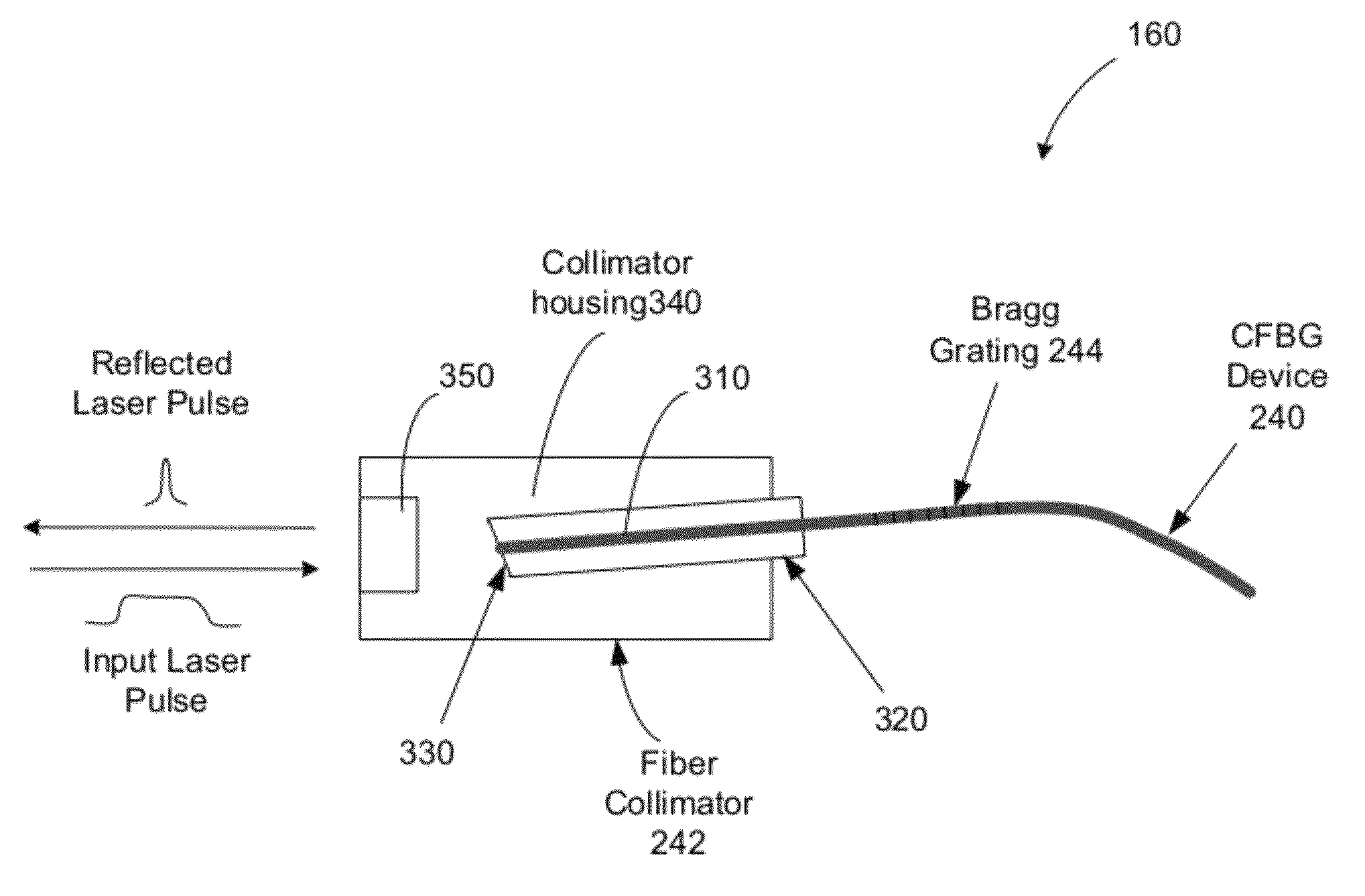
  • Summary
  • Abstract
  • Description
  • Claims
  • Application Information

AI Technical Summary

Benefits of technology

[0005]The present application discloses a compact fiber laser that include a CFBG compressor and micro optical components which reduce the fiber length and minimize nonlinear effect in the laser pulses, in comparison to conventional fiber laser systems.
[0006]The use of micro optical components in a CFBG pulse compressor makes the disclosed laser device compact. The use of free-space optical paths reduces lead fiber length (fiber terminal section) for CFBG shorter than 2 cm, a factor of 1 / 10 or smaller than the lead fiber length in conventional fiber laser systems. As a result, the nonlinear effects associated with CFBG compressor are reduced by a factor of 10-100 lower comparing to conventional fiber splicing techniques. The quality of the output amplified laser pulses is significantly improved.
[0007]Moreover, the disclosed CPA laser device can be made very robust. A ferrule is used to host a fiber lead, and the glass ferrule has the same thermal expansion coefficient to make the device stable over wide temperature range. It also reduces the mechanical stresses that the fiber lead produced in the CFBG. The thermal and mechanical stabilities are critical to providing stable dispersion effects in the CFBG pulse compressor.

Problems solved by technology

A major drawback of the conventional techniques is that the significant lead fiber length produces large non-linear effects which affect the quality of the output laser pulses.

Method used


Image

  • Fiber lasers for producing amplified laser pulses with reduced non-linearity
  • Fiber lasers for producing amplified laser pulses with reduced non-linearity
  • Fiber lasers for producing amplified laser pulses with reduced non-linearity

Examples


Embodiment Construction

[0019]Optical fiber can exhibit nonlinear optical effects when used in optical devices. Such nonlinear optical effects in optical fiber can be undesirable in some application while desirable in others.

[0020]For example, stimulated Raman Scattering (SRS) is a non-linear optical interaction of light and optical phonon in the material when the intensity of light at an optical wavelength exceeds a SRS threshold. When SRS occurs, a Raman signal is generated in the same propagation direction of the original light by the non-linear SRS process in the medium at a Raman frequency that is shifted from the optical frequency of the original light by a Raman frequency detuning. The Raman frequency is usually lower than the frequency of the original light and can be higher than the frequency of the original light. In SRS, the original light acts as the pump light for generating the Raman signal and the energy of the original light is depleted and is transferred into the Raman signal via the SRS p...


PUM

PropertyMeasurementUnit
lengthaaaaaaaaaa
lengthaaaaaaaaaa
lengthaaaaaaaaaa

Abstract

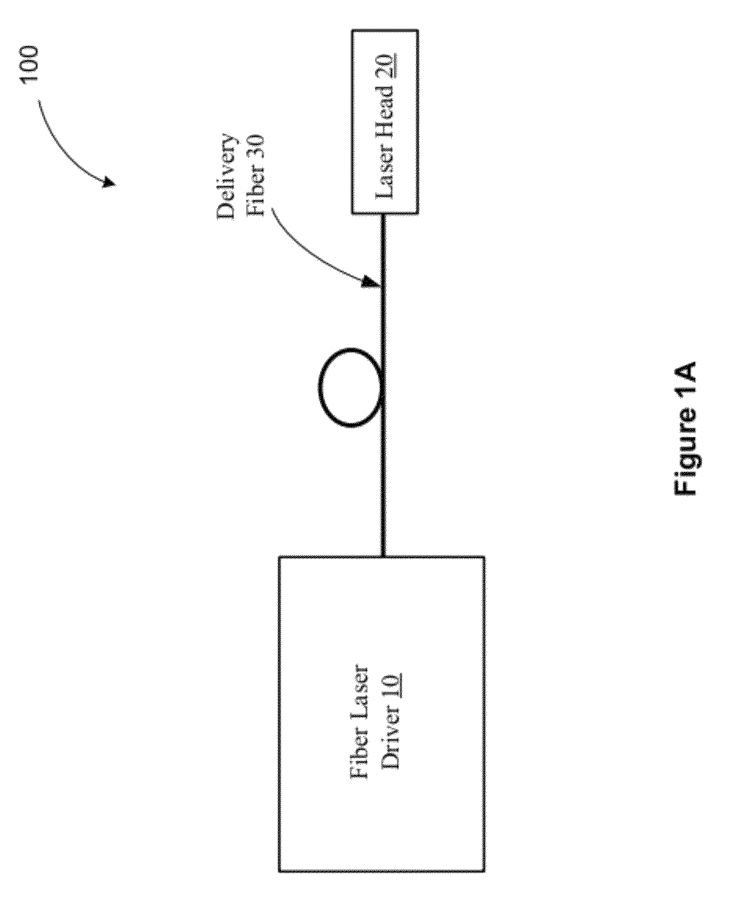
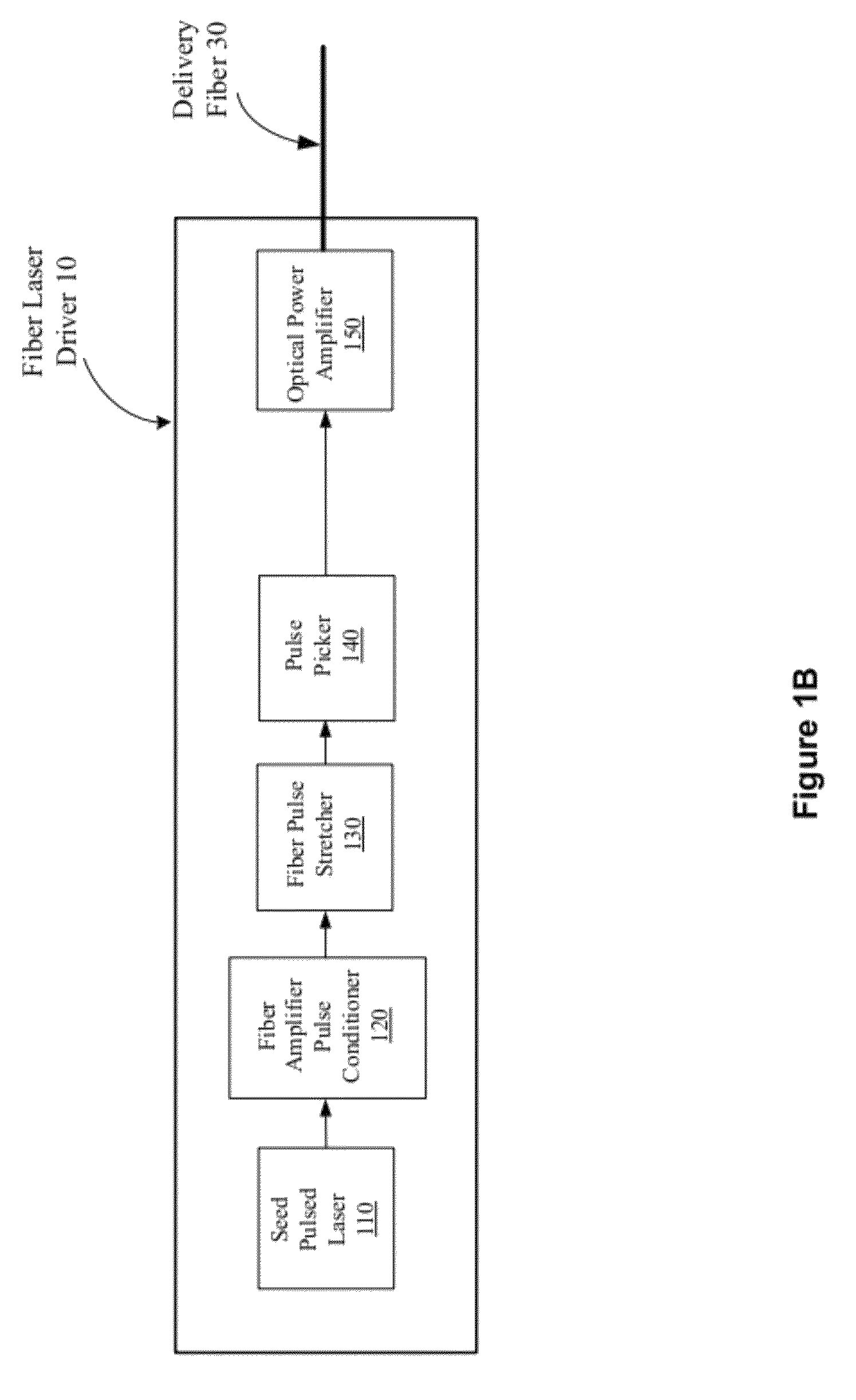
A chirped-pulsed amplification laser device includes a fiber laser driver, a laser head, and a delivery fiber that guides amplified stretched laser pulses from the laser driver to the laser head. The fiber laser driver includes a seed pulsed laser, a pulse stretcher, and an optical power amplifier. A chirped fiber Bragg grating compressor in the laser head includes a fiber terminal section configured to minimize broadening of the amplified stretched laser pulses, a chirped fiber Bragg grating section connected to the fiber terminal section and configured to compress and reflect amplified stretched laser pulses to produce reflected laser pulses with compressed pulse durations, and a collimator housing configured to fixedly hold a collimator lens and a ferrule. The ferrule holds the fiber terminal section tilted relative to an optical axis of the collimator lens.

Description

PRIORITY CLAIM[0001]The present patent application is a continuation-in-part application of and claims priority to U.S. patent application Ser. No. 12 / 829,364 entitled “Optical pulse compressing based on chirped fiber Bragg gratings for pulse amplification and fiber lasers”, filed Jul. 1, 2010, now U.S. Pat. No. 8,730,570 which claims the benefits of the U.S. provisional application No. 61 / 269,979 entitled “Chirped fiber Bragg grating (CFBG) optical pulse compressor for all fiber chirped pulse amplifier system” and filed by Anthony Hong Lin on Jul. 1, 2009, the entire disclosure of which is incorporated by reference as part of this document.BACKGROUND OF THE INVENTION[0002]This document relates to generation and control of laser pulses, including pulse compressor and laser pulse amplifiers and pulsed lasers.[0003]Various optical amplifiers are designed to amplify light by providing an optical gain at the same wavelength of the light to be amplified so that the light, after transmitt...

Claims


Application Information

Patent Timeline
Patent Type & Authority Patents(United States)
IPC IPC(8): G02F1/35H01S3/10H01S3/00H01S3/067H01S3/23H04B10/508
CPCH01S3/0057H04B10/508H01S3/06758H01S3/005H01S3/0092H01S3/2316
Inventor LIN, ANTHONEY, HONG
Owner CALMAR OPTCOM
Learn More