Image processing apparatus, image processing method and program

a technology of image processing and image processing method, applied in the field of image processing apparatus, can solve the problems of low correction rate or the like, generating banding, and scanning line interval error, so as to reduce the banding, suppress the density variation depending on the density of the dot, and improve the accuracy

Inactive Publication Date: 2014-09-16
CANON KK
View PDF21 Cites 9 Cited by
  • Summary
  • Abstract
  • Description
  • Claims
  • Application Information

AI Technical Summary

Benefits of technology

[0016]Another aspect of the present invention provides a technique of suppressing density variations depending on the dot density to reduce banding, and suppressing a decrease in the density of an isolated point upon suppressing density variations for banding.
[0017]Still another aspect of the present invention provides a technique of suppressing density variations depending on the scanning line density to reduce banding.
[0023]According to another aspect of the present invention, density variations depending on the dot density can be suppressed to reduce banding, and a decrease in the density of an isolated point, upon suppressing density variations for banding, can be suppressed.
[0024]According to still another aspect of the present invention, density variations depending on the scanning line density can be suppressed to reduce banding.

Problems solved by technology

For example, an image carrier speed error causes a scanning line interval error, generating banding.
A laser beam irradiation intensity error also generates banding.
Also, the correction rate or the like is not particularly calculated, and no satisfactory correction may be done.
However, color dots are not always formed on all lines aligned in the sub-scanning direction except for a solid image.
Banding cannot be corrected sufficiently.
However, if the predicted position of a scanning line or the exposure amount to be adjusted has an error, no banding can be corrected appropriately.

Method used


Image

  • Image processing apparatus, image processing method and program
  • Image processing apparatus, image processing method and program
  • Image processing apparatus, image processing method and program

Examples


first embodiment

Apparatus Arrangement

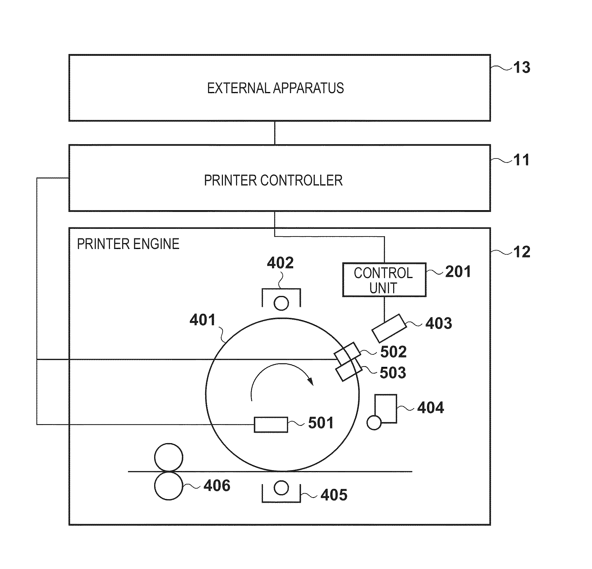
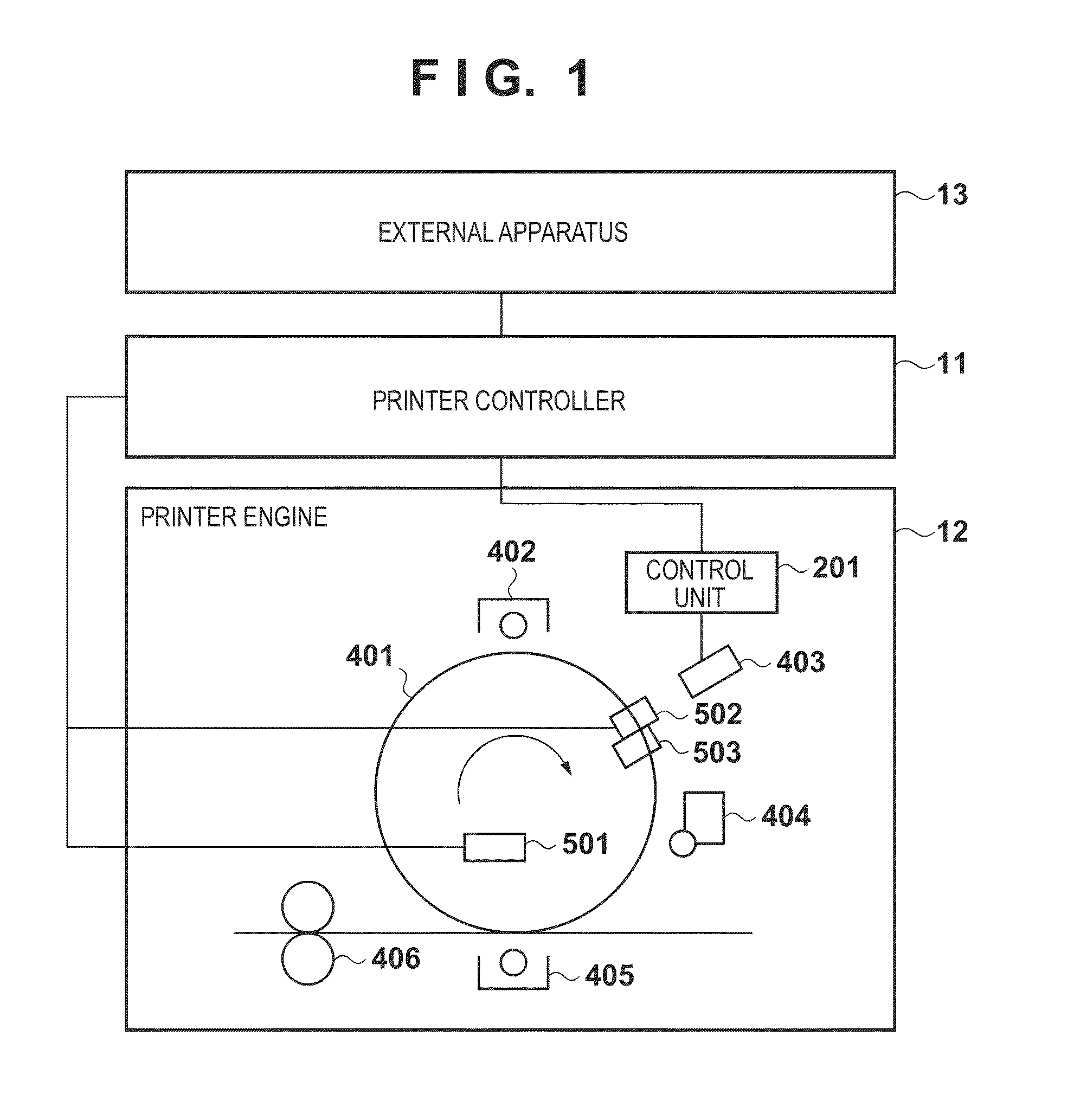
[0057]FIG. 1 is a view showing the arrangement of an image forming apparatus (an image processing apparatus) in the first embodiment. Referring to FIG. 1, an external apparatus 13 includes an interface with a hard disk drive, computer, server, network, or the like (none are shown), and inputs image data to a printer controller 11. The printer controller 11 receives input image data and performs halftone processing, exposure amount calculation processing, and exposure amount correction processing, details of which will be described later. The printer controller 11 transmits / receives a control instruction and information to / from a printer engine 12, and transmits image data to it.

[0058]The printer engine 12 includes a printer engine control unit 201, devices, and sensors. The devices are motors and the like used to drive the image carrier and paper conveyance system. The sensors are an encoder, optical position sensor, and the like. The printer engine control unit...

second embodiment

[0110]The second embodiment according to the present invention will be described. The first embodiment has described exposure amount correction in an image forming apparatus which performs exposure using one laser. The second embodiment will describe exposure amount correction in an image forming apparatus which includes a plurality of lasers for simultaneous scanning and performs interlaced exposure.

[0111]Apparatus Arrangement

[0112]The image forming apparatus (the image processing apparatus) in the second embodiment includes a multi-laser scanner 407 with a plurality of lasers, in place of the laser scanner 403 with one laser which is used in the arrangement shown in FIG. 1 in the first embodiment. The image forming apparatus in the second embodiment performs interlaced exposure to form a plurality of scanning lines at intervals each of a predetermined number of scanning lines by one exposure scanning of the multi-laser scanner 407.

[0113]FIG. 11 is a block diagram showing an arrang...

third embodiment

Exposure Amount Control

[0134]Exposure amount control in the third embodiment will be described with reference to the flowchart of FIG. 17. The arrangement of an image forming apparatus (an image processing apparatus) in the third embodiment is the same as that shown in FIG. 1 in the first embodiment, and a description thereof will not be repeated. As described above, control (to be referred to as exposure amount control) of the intensity (or emission time) of a laser beam L needs to consider a dot pattern around the dot of interest. Note that processing shown in FIG. 17 is executed in every main scanning of the laser beam and repeated by the number of pixels (number of lines) of one image in the sub-scanning direction. An arrangement which performs exposure amount control will be exemplified with reference to the block diagram of FIG. 18.

[0135]A scanning line position calculation unit 2104 in a printer controller 11 calculates a scanning line position error on a scanning line n, and...


PUM


Abstract

There is provided an image forming apparatus comprising: detection means for detecting position information indicating a scanning position; interval prediction means for predicting a first scanning line interval indicating a distance in the sub-scanning direction between the scanning line of interest and a succeeding scanning line to be scanned after the scanning line of interest; interval calculation means for calculating, by using the position information held by the holding means, a second scanning line interval indicating a distance in the sub-scanning direction between the scanning line of interest and the scanned scanning line; and rate calculation means for calculating a correction rate on an exposure amount for the scanning line of interest so that a predicted density calculated using the first scanning line interval and the second scanning line interval matches with a predicted density calculated using a predetermined reference scanning line interval.

Description

TECHNICAL FIELD[0001]The present invention relates to an image processing apparatus which forms an electrostatic latent image on an image carrier by exposing and scanning the image carrier, and a control method thereof.BACKGROUND ART[0002]Generally, an electrophotographic image forming apparatus forms an image by exposing a photosensitive body (image carrier) such as a photosensitive drum or photosensitive belt with a laser beam or the like to form an electrostatic latent image corresponding to an image signal, developing the electrostatic latent image, and transferring it onto a printing medium or the like. At this time, the laser beam is scanned sequentially one-dimensionally in the main scanning direction, for example, from left to right. At the same time, the laser beam is scanned in a direction almost perpendicular to the main scanning direction, for example, from top to bottom. On the image carrier, many straight lines (to be referred to as scanning lines) in the main scanning...

Claims


Application Information

Patent Timeline
Patent Type & Authority Patents(United States)
IPC IPC(8): H04N1/04B41J2/47G03G15/00G02B26/08A61B8/14B41J2/455G03G15/043G06K15/12H04N1/40
CPCH04N1/40093G03G15/043G06K15/1219G06K15/1209
Inventor TAKIKAWA, YOICHIKUBO, HIDEKIOCHIAI, TAKASHI
Owner CANON KK
Why Eureka
Try Eureka