Analog controller for inverter

Inactive Publication Date: 2014-09-23
NAT CHENG KUNG UNIV
View PDF4 Cites 4 Cited by
  • Summary
  • Abstract
  • Description
  • Claims
  • Application Information

AI Technical Summary

Benefits of technology

[0023]The present invention is to adaptively adjust conduction time under different irradiance and temperature for obtaining an optimized relationship between the inverter and the power generating devic

Problems solved by technology

However, these techniques are complicated and difficult in implementation.
The shortcoming of using digital circuits is that the precision of the controller is limited by the number of bits of the micro

Method used


Image

  • Analog controller for inverter
  • Analog controller for inverter
  • Analog controller for inverter

Examples


Embodiment Construction

[0032]The foregoing objects, features and advantages adopted by the present invention can be best understood by referring to the following detailed description of the preferred embodiments and the accompanying drawings. Furthermore, the directional terms described in the present invention, such as upper, lower, front, rear, left, right, inner, outer, side and etc., are only directions referring to the accompanying drawings, so that the used directional terms are used to describe and understand the present invention, but the present invention is not limited thereto.

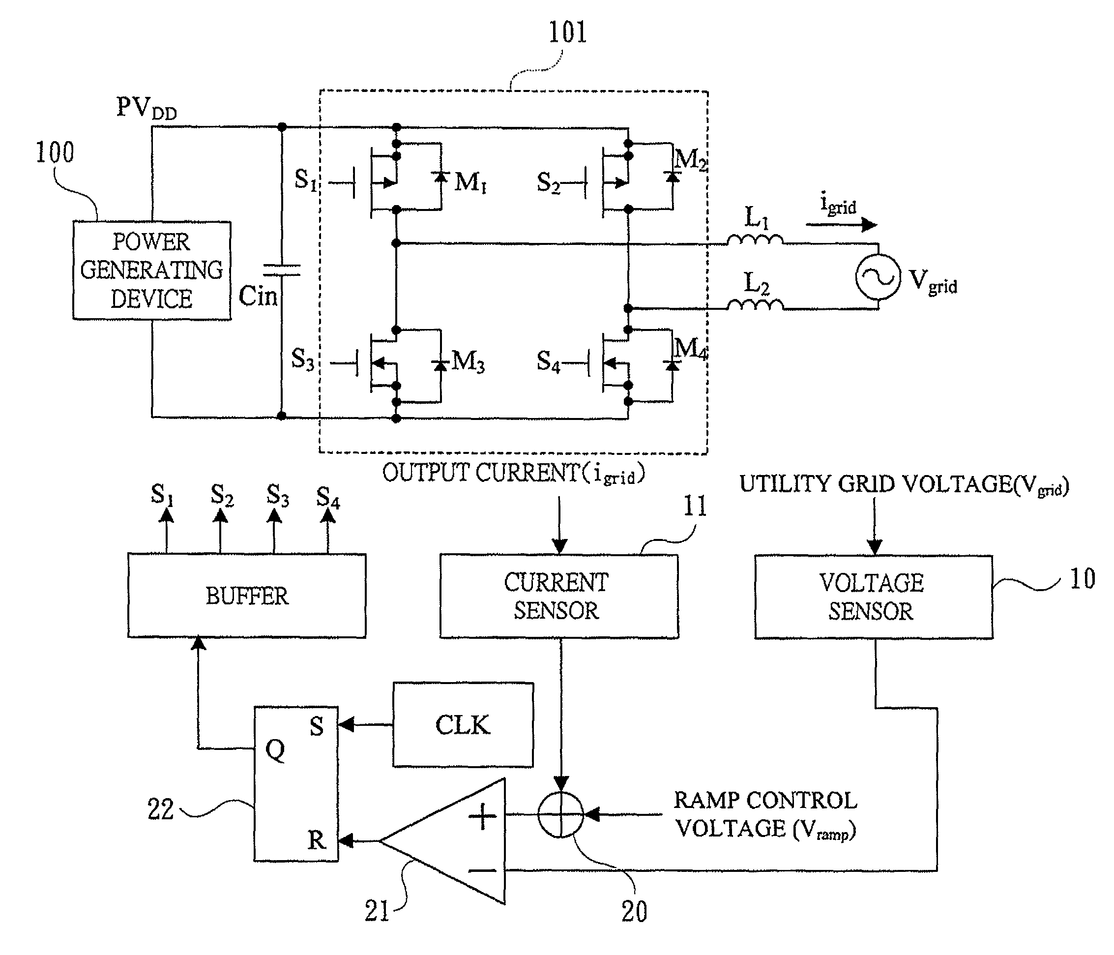
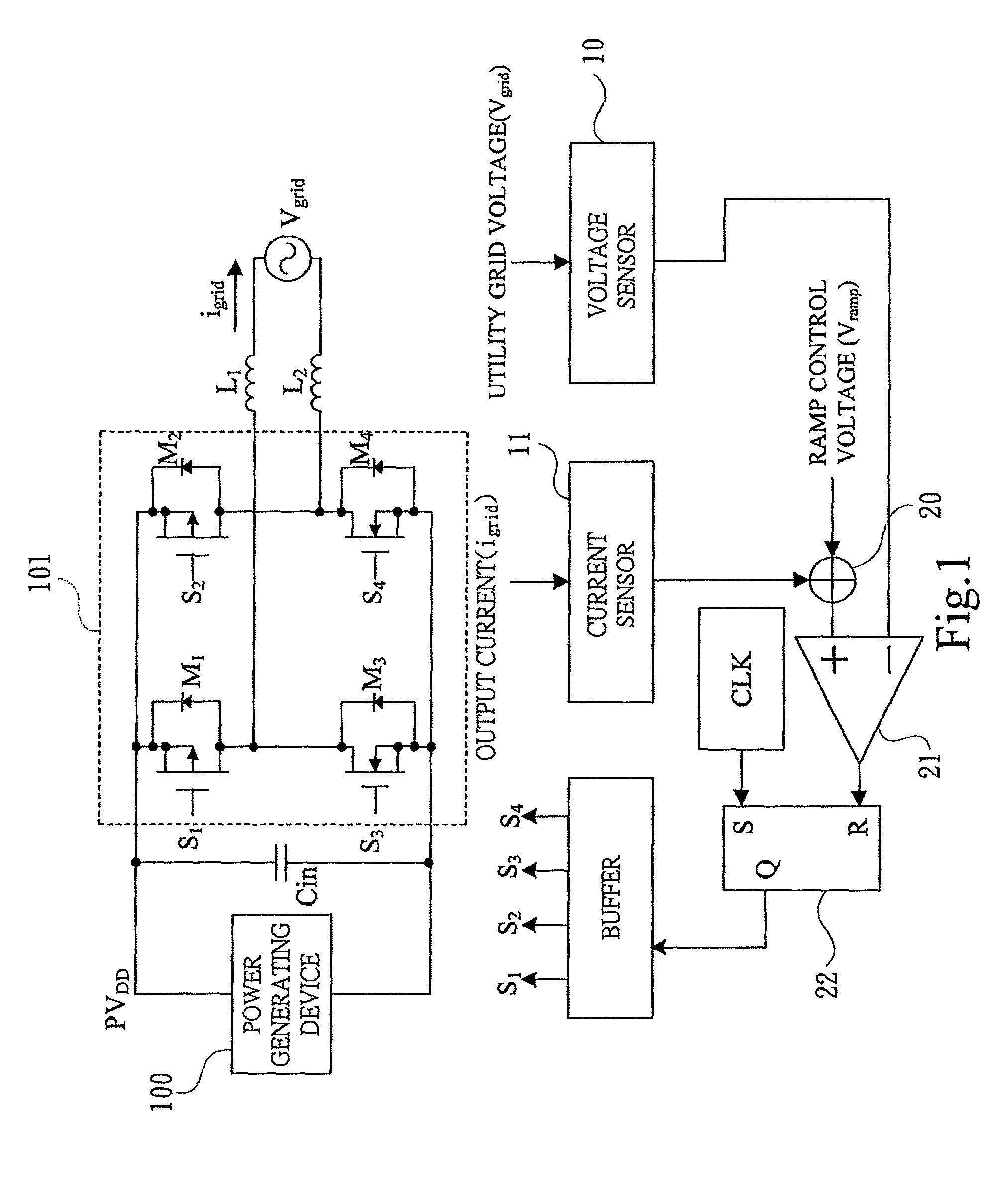
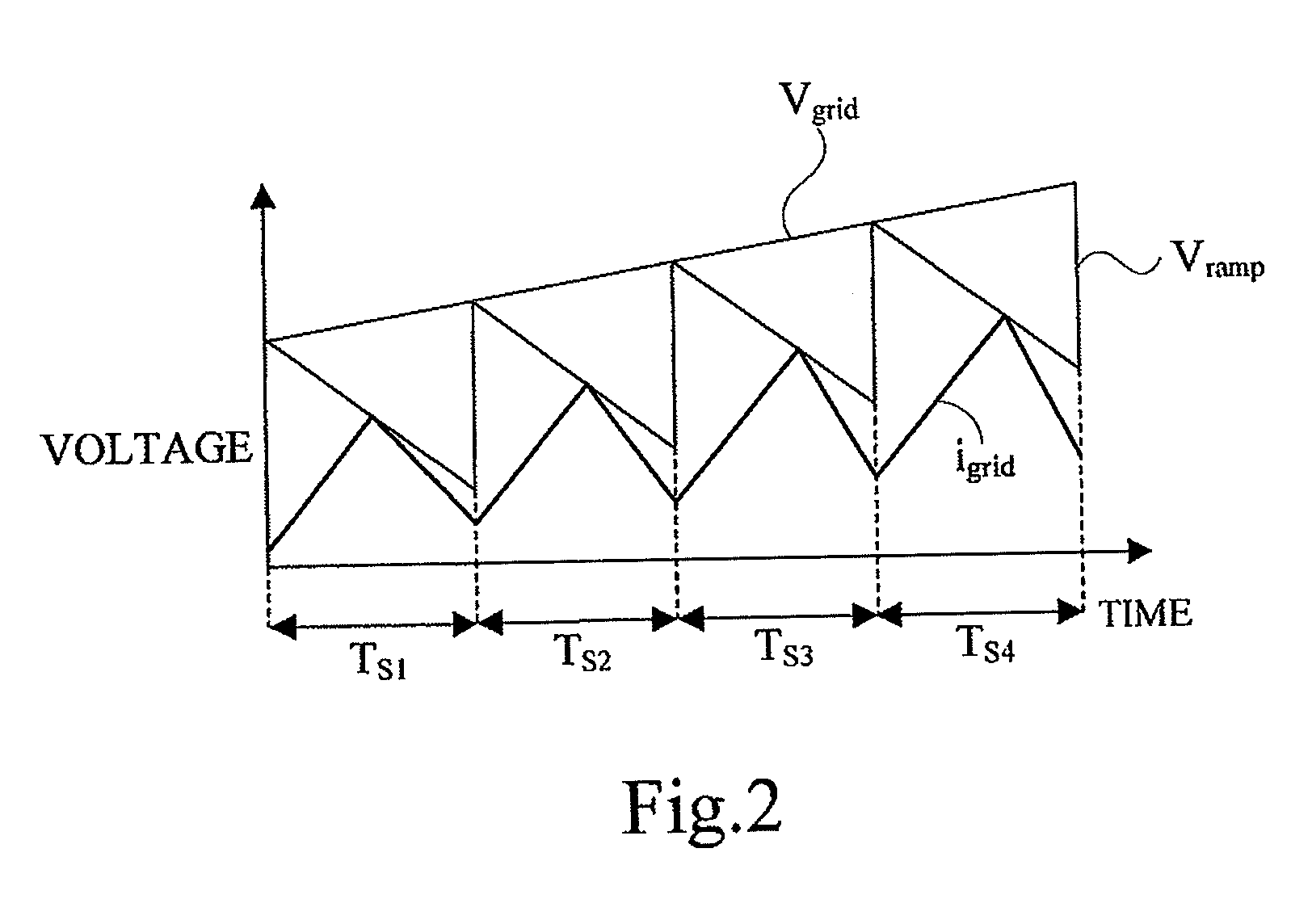
[0033]Please refer to FIGS. 1, 2 and 3, wherein FIG. 1 schematically shows a control structure of a preferred embodiment of an analog controller for an inverter in accordance with the present invention; FIG. 2 shows waveforms of control signals of a preferred embodiment of the analog controller for an inverter; and FIG. 3 schematically shows a preferred embodiment of a maximum power tracking (hereafter “MPPT”) algorithm ci...


PUM


Abstract

An analog controller is disclosed. The controller has a maximum power point tracking unit and a power factor adjusting unit. The maximum power point tracking unit generates a maximum power tracking voltage which is used to control the magnitude of the output current of the inverter so as to extract the most available power from the power generating device. The power factor adjusting unit, which generates a ramp control voltage that will further determine the duty ratio and switching frequency of PWM signal, gracefully tunes the magnitude and reduces the total harmonic distortion of the current injected from inverter into utility grid.

Description

BACKGROUND OF THE INVENTION[0001]1. Field of the Invention[0002]The present invention concerns an analog control device, especially to an analog controller for an inverter which is fed by a power generating device with direct current and feeds the utility grid with alternate current. The power generating device, preferably solar panel, generates electricity from renewable energy sources.[0003]2. Description of the Related Art[0004]The output power of power generating device that captures solar or wind energy can be changed due to different environmental conditions. Therefore, maintaining optimized power conversion efficiency with stable in-phase output current of an inverter is an essential design consideration for a controller.[0005]With reference to FIG. 7, a system diagram of a conventional two-stage solar-energy power generating apparatus is disclosed. The two-stage solar-energy power generating apparatus includes a solar panel 90, a maximum power point tracking (hereafter “MPPT...

Claims


Application Information

Patent Timeline
IPC IPC(8): H02M7/5387H02M7/42H02J3/38H02M1/42
CPCH02M7/5387H02J3/385H02M1/42Y02B70/12Y02E10/58Y10S323/906H02J2300/26H02J3/381Y02B70/10Y02E10/56
Inventor KUO, YEONG-CHAULIU, WEN-CHUENKUO, TAI-HAUR
Owner NAT CHENG KUNG UNIV
Why Eureka
Try Eureka