Central tire inflation wheel assembly, valve and central tire inflation system
a technology of central tire inflation and tire inflation, which is applied in the direction of mechanical equipment, transportation and packaging, functional valve types, etc., can solve the problems of valve failure, valve damage, and increased cost and complexity of valves, so as to increase improve the longevity of valves, and simplify the valve construction.
- Summary
- Abstract
- Description
- Claims
- Application Information
AI Technical Summary
Benefits of technology
Problems solved by technology
Method used
Image
Examples
first embodiment
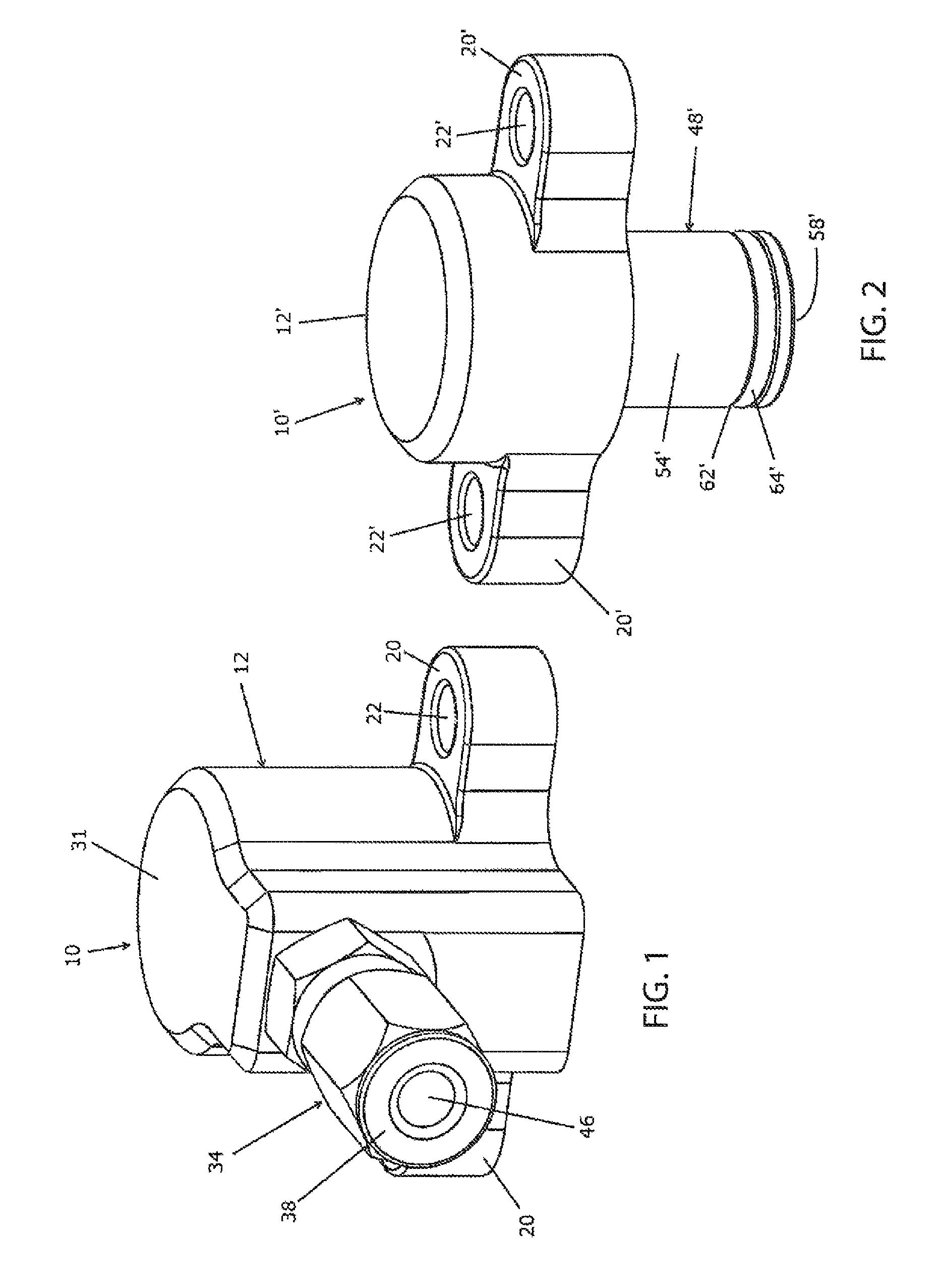
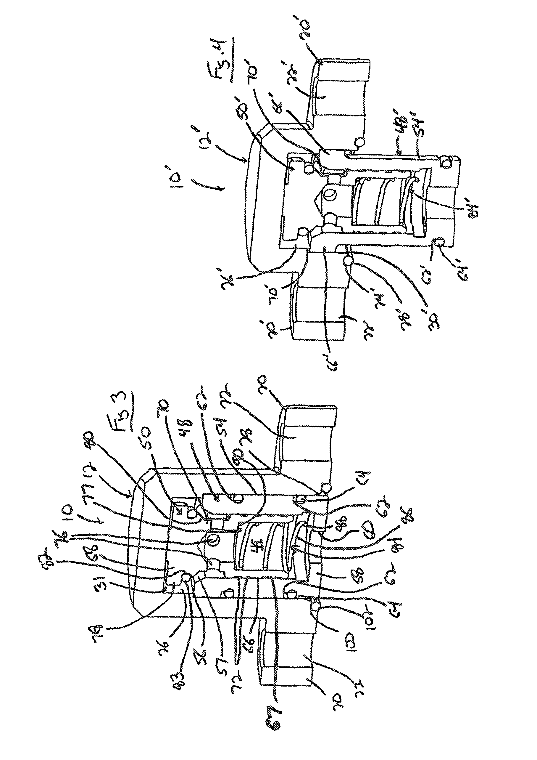
[0043]With reference now to the drawing figures in which like reference numerals designate like parts throughout the disclosure, a wheel valve constructed according to the present invention is indicted at 10 in FIGS. 1, 3 and 5-7. The valve 10 includes a casing 12 that is secured to the rim 14 of a wheel 16 adapted to support a tire (not shown) thereon. The rim 14 includes a number of air passages or channels 18 formed therein, with the casing 12 mounted over or otherwise in communication with one of the passages 18. The casing 12 is mounted flush against the rim 14 in any suitable manner to maintain an air-tight engagement between the casing 12 and the rim 14. In a preferred embodiment, the casing 12 includes a pair of flanges 20 extending outwardly from the casing 12 that include bores 22 formed therein. The bores 22 receive suitable fasteners 23 therethrough that are engaged with the rim 14 to affix the casing 12 to the rim 14. In a preferred embodiment, the flanges 20 are integr...
second embodiment
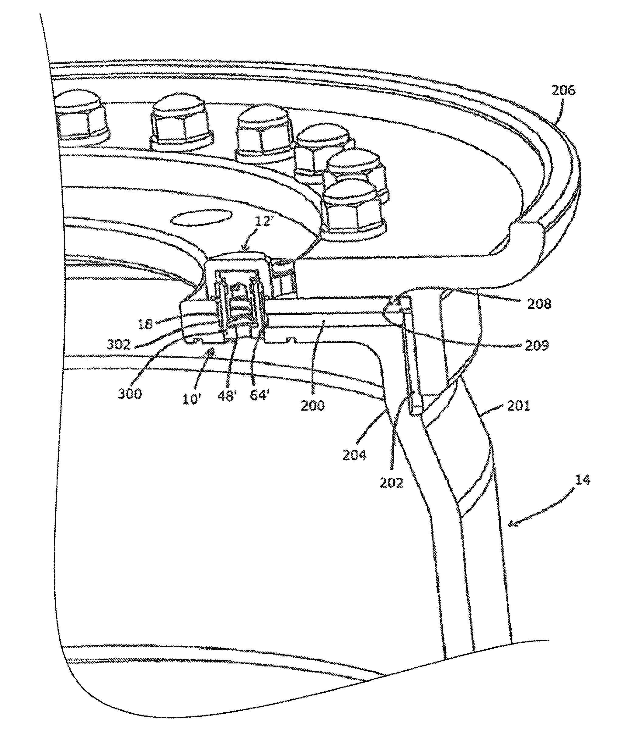
[0053]Looking now at FIGS. 2, 4, and 8-11, the valve 10′ is illustrated. In this embodiment, the valve 10′, instead of being mounted flush with the rim 14, as for valve 10, is mounted within the passage 18, such that the valve 10′ is recessed within the rim 14 to lessen exposed portion of the valve 10′ relative to the valve 10, and consequently reduce the potential for objects striking and damaging the valve 10′. The passage 18 is formed within a rim 14 having an inner rim 201 and is connected to an air channel 200 formed in the inner rim 201 in any suitable manner, such as by drilling, though the rim 14 to the passage 18, and channel 200 could also he formed in the outer rim 206, or between the outer rim 206 and the inner rim 201, if necessary. The channel 200 terminates in a groove 202 formed in a peripheral wall 204 of the inner rim 201, and that preferably extends radially inwardly from the channel 200 towards the center of the peripheral wall 204 of the inner rim 201. When an o...
third embodiment
[0072]Looking now at FIGS. 23-26, the manifold 700 is illustrated. The manifold 700 for each tire 1006 operably connected thereto includes a PO check valve assembly 7001, a PO check seat 701, a PO check activation piston 702, a pilot pressure port 703, a pressure sensor 704, a control circuit board 705, a control box housing 706, a check valve 707, and exhaust passage 708 to the valve 707, a connection 709 to the wheel valve 10, 10′, a secondary exhaust orifice 710, a primary exhaust orifice 711, a pressurized air passage 712 connected to the compressed air source 1002, a solenoid valve 713, and a PO check exhaust passage 714. The manifold 700 also includes a compressor inlet 715 that connects to each pressure passage 712, a PO check exhaust port 716, an exhaust valve 717 and a POC valve 718.
[0073]In FIG. 26 the system 1000 including the manifold 700 is schematically illustrated. The goal of the Independent CTIS 1000 is to allow for monitoring, inflating & deflating each tire 1006 i...
PUM
 Abstract
Description
Claims
Application Information
 - R&D
- Intellectual Property
- Life Sciences
- Materials
- Tech Scout
- Unparalleled Data Quality
- Higher Quality Content
- 60% Fewer Hallucinations
Browse by: Latest US Patents, China's latest patents, Technical Efficacy Thesaurus, Application Domain, Technology Topic, Popular Technical Reports.
© 2025 PatSnap. All rights reserved.Legal|Privacy policy|Modern Slavery Act Transparency Statement|Sitemap|About US| Contact US: help@patsnap.com


