Method for processing froth treatment tailings
a technology of froth treatment and tailings, which is applied in the direction of hydrocarbon oil treatment, flotation, liquid hydrocarbon mixture production, etc., can solve the problem that the significant amount of bitumen from the original oil sand ore is therefore typically lost to the froth treatment tailings, and achieves the effect of enhancing the recovery of the amount of diluen
- Summary
- Abstract
- Description
- Claims
- Application Information
AI Technical Summary
Benefits of technology
Problems solved by technology
Method used
Image
Examples
example 1
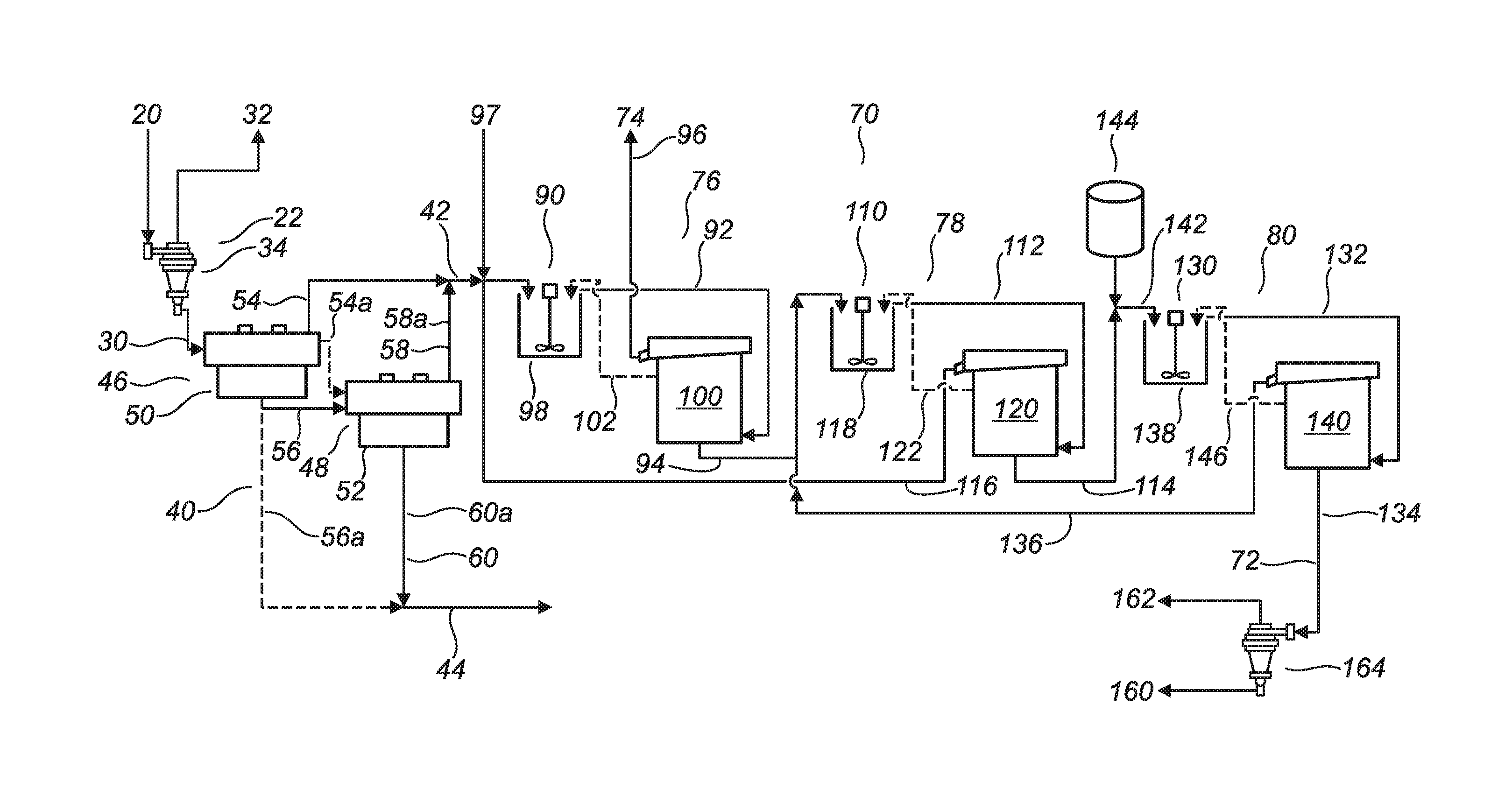
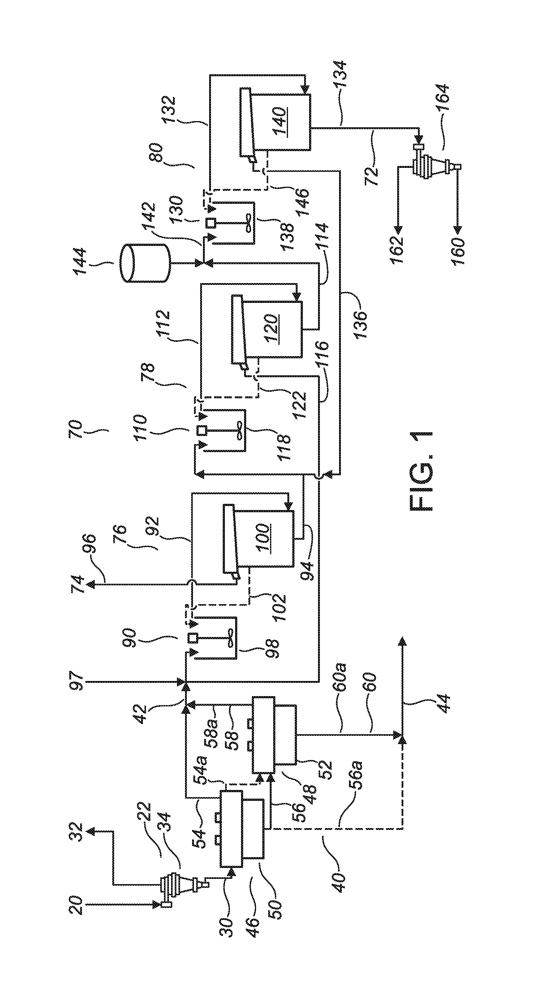
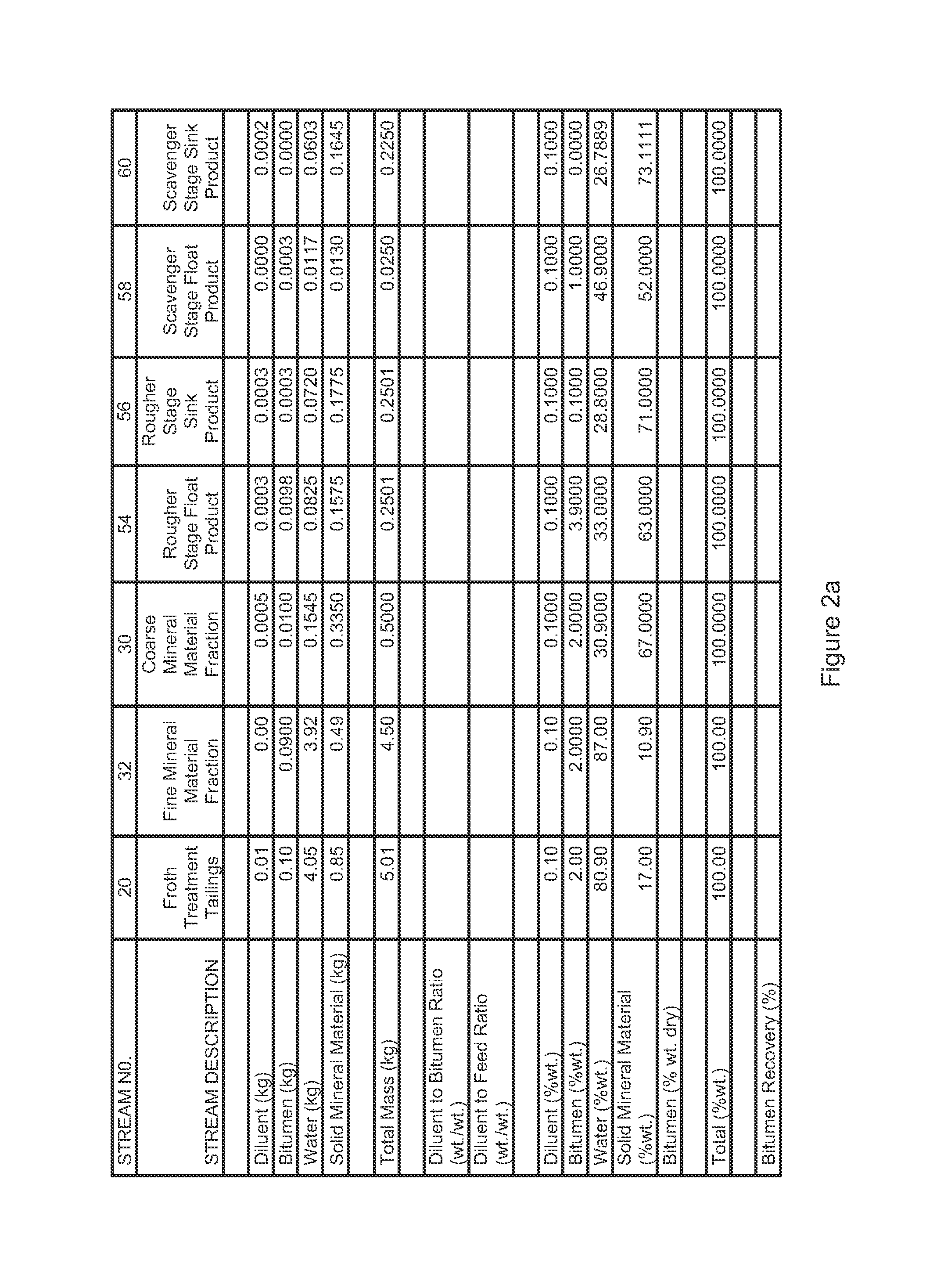
[0202]Referring to FIG. 2, a material balance is provided for a bench scale test simulating the embodiment of the invention depicted by the solid lines in FIG. 1. The material balance of FIG. 2 does not include a simulation of the alternate or optional features which are depicted by the dashed lines in FIG. 1. Consequently, in the material balance of FIG. 2, the froth flotation (40) is arranged in a scavenging configuration, and the solvent extraction (70) does not include recycling of the solvent extraction intermediate components (102,122,146).
[0203]In the bench scale test which is represented by FIG. 2, the solvent extraction (70) was performed by adding “fresh” naphtha as a hydrocarbon diluent in each of the three solvent extraction stages (76,78,80) instead of by recycling the overflow components (116,136) from the second and third solvent extraction stages (78,80) respectively. The overflow components (116,136) were, however, taken into consideration in calculating the materia...
example 2
[0211]Referring to FIG. 3, a material balance is provided for a heavy mineral concentrate produced by a bench scale test simulating a froth flotation (40) performed according to the embodiment of FIG. 1, including a rougher froth flotation stage and a scavenger froth flotation stage.
[0212]Referring to FIG. 3, it is noted that about 97.5 percent of the total heavy minerals contained in the coarse mineral material fraction (30) were recovered in the heavy mineral concentrate (42), about 81.6 percent of the hydrocarbons contained in the coarse mineral material fraction (30) were recovered in the heavy mineral concentrate (42), about 97.5 percent of the TiO2 values contained in the coarse mineral material fraction (30) were recovered in the heavy mineral concentrate (42), and about 99.1 percent of the ZrO2 values contained in the coarse mineral material fraction were recovered in the heavy mineral concentrate (42).
example 3
[0213]Referring to FIG. 4, a graph is provided of data obtained from bench scale tests of one stage, two stage, and three stage solvent extractions (70) performed according to the invention a different diluent amounts in the feed material, depicting bitumen concentration of a debitumenized heavy mineral concentrate (72) by dry weight of the debitumenized heavy mineral concentrate (72) as a function of diluent amount and as a function of the number of solvent extraction stages.
[0214]Referring to FIG. 4, it is noted that a bitumen concentration of less than about 0.5 percent by dry weight of the debitumenized heavy mineral concentrate (72) was achieved by a three stage solvent extraction in which the diluent amount was at least 15 percent by weight of the feed material.
PUM
| Property | Measurement | Unit |
|---|---|---|
| density | aaaaa | aaaaa |
| viscosity | aaaaa | aaaaa |
| particle size | aaaaa | aaaaa |
Abstract
Description
Claims
Application Information
 - R&D
- Intellectual Property
- Life Sciences
- Materials
- Tech Scout
- Unparalleled Data Quality
- Higher Quality Content
- 60% Fewer Hallucinations
Browse by: Latest US Patents, China's latest patents, Technical Efficacy Thesaurus, Application Domain, Technology Topic, Popular Technical Reports.
© 2025 PatSnap. All rights reserved.Legal|Privacy policy|Modern Slavery Act Transparency Statement|Sitemap|About US| Contact US: help@patsnap.com


