
Receiver, transmitter, feedback device, transceiver and signal processing method

a transceiver and feedback technology, applied in the field of communication technologies, can solve the problems of high cost, large volume of the apparatus, and high power consumption, and achieve the effect of reducing the volume and power consumption of the apparatus and reducing the cos

Active Publication Date: 2014-10-07
HUAWEI TECH CO LTD
View PDF32 Cites 5 Cited by
  • Summary
  • Abstract
  • Description
  • Claims
  • Application Information

AI Technical Summary

Benefits of technology

This patent describes a device and methods for reducing the size, power consumption, and cost of equipment used to process signals in multiple frequency bands. The invention allows for the use of a transmitter feedback device, a transmitter, a receiver, a transceiver, and a method for processing a transmitter feedback signal and a method for transmitting a multi-frequency band signal. This approach can efficiently use multiple radio frequency channels and feedback signals, resulting in a smaller and more cost-effective apparatus.

Problems solved by technology

However, for the practice that multiple radio frequency transceiver channels are integrated in one same system in a package or an IC by using the highly integrated semiconductor process, there is a problem whether an isolation degree and performance of the radio frequency signal of different frequency bands can satisfy protocol requirements.
When multiple sets of discrete components directly constitute multiple radio frequency channels to process different frequency band signals, the problem of the isolation degrees and the performance of different frequency bands may be solved, but the problems that the apparatus has a huge volume, high power consumption, and a high cost occur.

Method used


Image

  • Receiver, transmitter, feedback device, transceiver and signal processing method
  • Receiver, transmitter, feedback device, transceiver and signal processing method
  • Receiver, transmitter, feedback device, transceiver and signal processing method

Examples


Embodiment Construction

[0032]The present invention is described in all rounds with reference to the accompanying drawings. In the accompanying drawings, a same mark represents a same or similar component or a same or similar element.

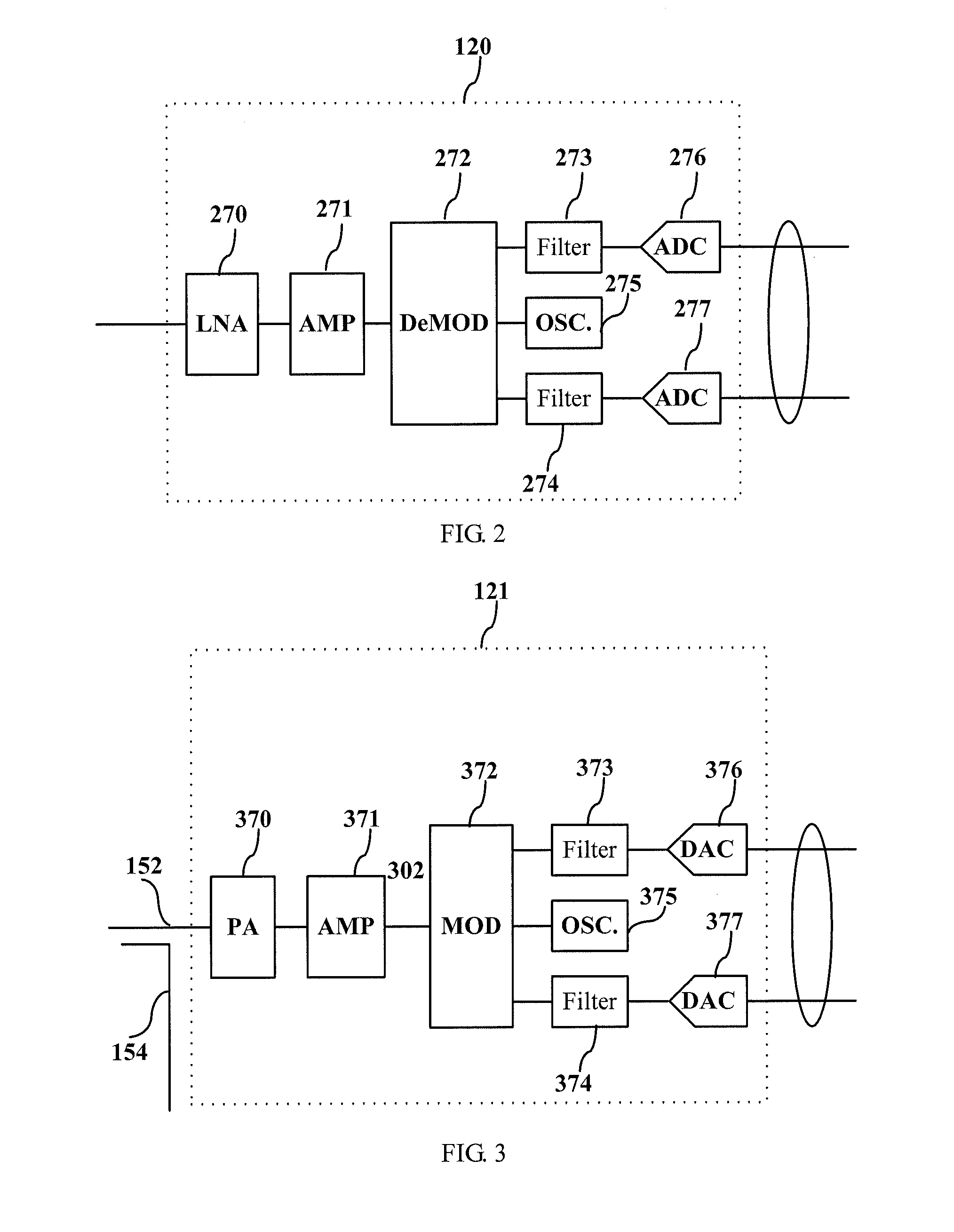
[0033]In the embodiments in the following, the following English abbreviations have the following meaning, DAC refers to a digital analog converter (Digital Analog Converter, DAC), ADC refers to an analog digital converter (Analog Digital Converter, ADC), SAW refers to a surface acoustic wave (Surface Acoustic Wave), and DPD refers to digital pre-distortion (Digital Pre-Distortion).

[0034]In this embodiment, a multi-frequency band signal refers to a signal including two or more frequency bands; a central frequency of multiple (pieces of) frequency bands refers to an intermediate value between a highest frequency and a lowest frequency in all the frequency bands; and the central frequency of each frequency band refers to the intermediate value between the highest frequency and t...


PUM


Abstract

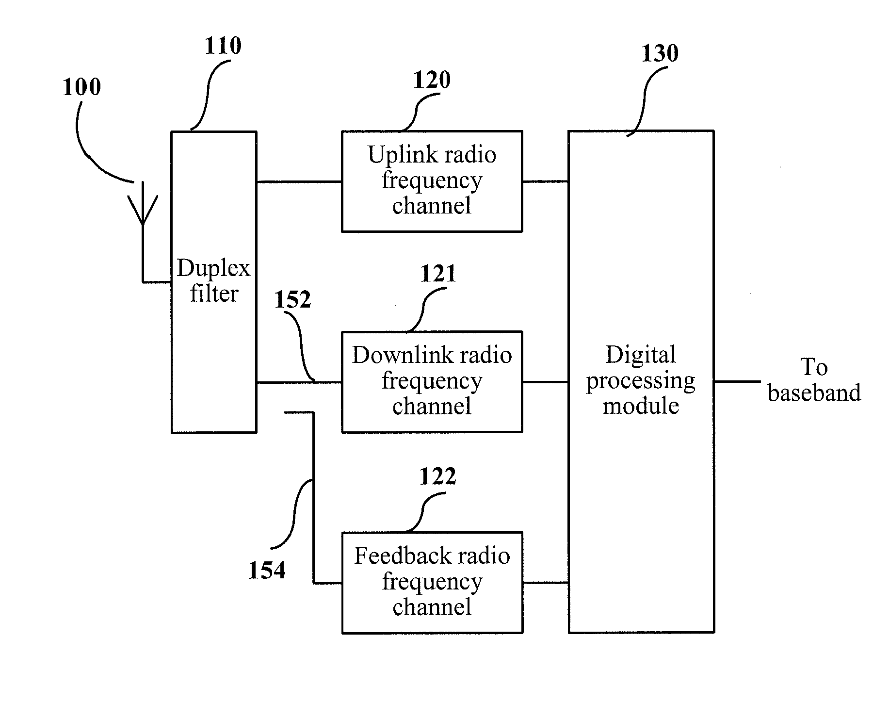
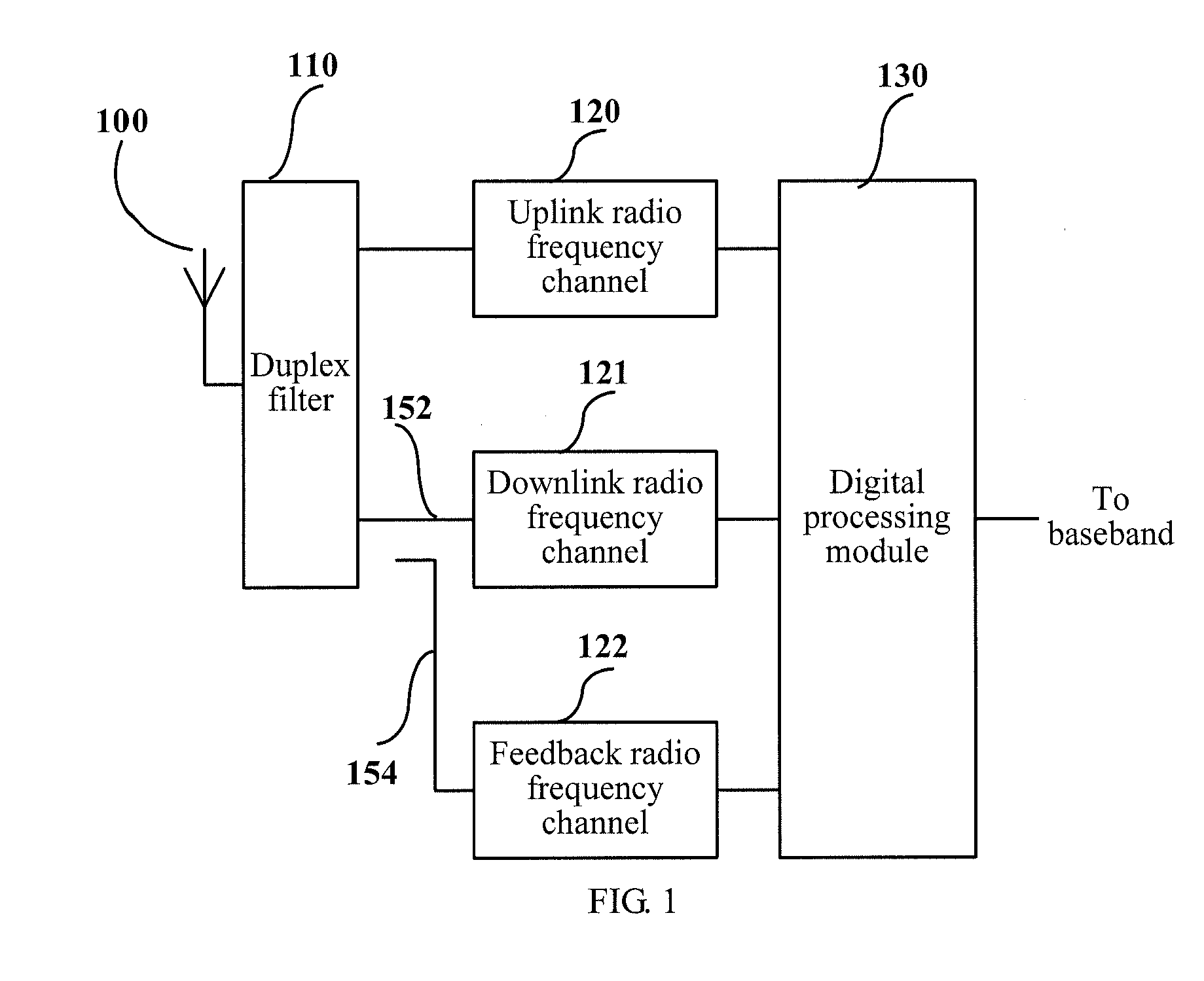
The present invention provides a receiver, a transmitter, a transmitter feedback device, and corresponding methods. The feedback device includes: a multi-channel frequency selection band-pass circuit, configured to receive a multi-frequency band feedback signal, and output a feedback signal of each frequency band in a time-division manner; a feedback local oscillator, configured to provide feedback local oscillation corresponding to each frequency band in a time-division manner; a mixer, configured to mix the feedback signal of each frequency band from the multi-channel frequency selection band-pass circuit and the feedback local oscillation corresponding to each frequency band from the feedback local oscillator, and output an intermediate frequency signal of each frequency band in a time-division manner. A solution in which only one set of signal processing channels is used to process the signals of multiple frequency bands in the uplink, the downlink or both the uplink and downlink is provided.

Description

CROSS-REFERENCE TO RELATED APPLICATIONS[0001]This application is a continuation of International Application No PCT / CN2011 / 070420, filed on Jan. 20, 2011, which claims priority to Chinese Patent Application No. 201010000798.1, filed on Jan. 20, 2010, all of which are hereby incorporated by reference in their entireties.FIELD OF THE INVENTION[0002]The present invention relates the field of communications technologies, and in particular, to a receiver, a transmitter, a transmitter feedback device, a transceiver, a method for transmitting a multi-frequency band signal, a method for receiving a multi-frequency band signal, and a method for processing a transmitter feedback signal.BACKGROUND OF THE INVENTION[0003]The wireless communication technology has undergone development phases from analog communication to digital communication, from single carrier (Single carrier) communication to multi-carrier (Multi-carrier) communication, from single-mode (Single-Mode) communication to multi-mod...

Claims


Application Information

Patent Timeline
Patent Type & Authority Patents(United States)
IPC IPC(8): H04J3/14H04B1/04H04L27/00H04L27/36
CPCH04L27/364H04B1/0475H04L27/368H04B2001/0433H04L2027/0016H04L2027/002H04L27/14H04L27/26H04L27/12H03F1/34H03F3/24
Inventor HUANG, BAOPING
Owner HUAWEI TECH CO LTD
Learn More