Node, data processing system, and data processing method

a data processing system and node technology, applied in the field of communication, can solve the problems of increasing the flow of communications networks, increasing the requirements of increasing the requirements of the capacity and power consumption of the router in the node, so as to reduce the number of nodes, reduce the number of connections, and increase the number of available connections.

Active Publication Date: 2011-04-28
HUAWEI TECH CO LTD
View PDF10 Cites 58 Cited by
  • Summary
  • Abstract
  • Description
  • Claims
  • Application Information

AI Technical Summary

Benefits of technology

[0009]The present invention is directed to a node, a data processing system, and a data processing method, capable of overcoming defects in the prior art that the volume of the node is large, the power consumption is heavy, the costs are high, and a data conflict is generated on the optical layer in all optical switching, so as to reduce the volume, the power consumption, and the costs of the nodes, and avoid the problem of generation of data conflict on the optical layer in all optical switching.
[0019]In the technical solutions of the present invention, by dividing a plurality of OB paths on a wavelength, service data may be transferred between the nodes of the data processing system through the OB paths, thereby reducing the connection bandwidth between the nodes. A plurality of OB paths may exist on a port or ports of the node, so that the node may be connected to more nodes through a plurality of OB paths, thereby increasing the number of available connections of the node. Meanwhile, for one node, in a situation of having the same number of connections, the number of the ports of the node may be reduced, thereby reducing the volume, power consumption, and costs of the node. The OB paths may be configured and relatively fixed, and the node performs the cross-connection process on the OB paths according to the OB configuration information, thereby avoiding the problem of generation of data conflict on the optical layer due to lack of optical buffers in all-optical switching. The node completes, on the optical layer, the synchronization process and the cross-connection process on the OB paths, thereby simplifying an optical-to-electrical conversion procedure, an electrical-to-optical conversion procedure, and an electrical processing procedure, so as to reduce the power consumption, the volume, and the costs of the node.

Problems solved by technology

As wideband services are developed and the number of wideband users increases, the network flow in the communications network exponentially increases, so that requirements on capacity and power consumption of the router in the node become increasingly higher.
Currently, in order to support the transfer of the service data in the communications network, the capacity and the power consumption of the router have been developed to an unendurable extent, and the capital costs and operational costs are high.
Therefore, it is a problem to be solved urgently how to reduce the capacity and the power consumption of the router in the node, that is, to reduce the capacity and the power consumption of the node, especially, the power consumption of the node.
However, in the implementation of the present invention, the inventor finds that the prior art has at least the following problems.
In the technical solution of the first prior art, the granularity of the service data is large when passing through the wavelength layer or the ODU layer on the node, so that a bandwidth is excessively large when the nodes are connected by using the wavelength or the ODU path.
When the node needs to be connected to more nodes, the number of the required paths is enormous, the number of the required connections is increased, and the node needs to provide more ports for connecting to more nodes, so that the volume, the power consumption, and the costs of the node are increased.
In the second prior art, although the power consumption of the node is reduced, the OBS lacks appropriate optical buffers, and thus a data conflict may easily occur on the optical layer when the data is transmitted in the OBS system.

Method used


Image

  • Node, data processing system, and data processing method
  • Node, data processing system, and data processing method
  • Node, data processing system, and data processing method

Examples


first embodiment

[0045]FIG. 4 is a schematic structural view of a node according to the present invention. Referring to FIG. 4, the node includes a control module 11, a synchronization processing module 12, and a cross-connection module 13. The control module 11 is adapted to generate synchronization information, and send the synchronization information to the synchronization processing module 12. The control module 11 is further adapted to generate OB configuration information, and send the OB configuration information to the cross-connection module 13. The synchronization processing module 12 performs a synchronization process on OB paths at one or more wavelengths according to the synchronization information. Then, the cross-connection module 13 performs, according to the OB configuration information, a cross-connection process on the OB paths, on which the synchronization process has been performed. In this embodiment, one or more synchronization processing modules 12 are provided, but only one ...

second embodiment

[0047]FIG. 5 is a schematic structural view of a node according to the present invention. Referring to FIG. 5, the node includes a control module 11, a synchronization processing module 12, and a cross-connection module 13. The control module 11 includes a detecting unit 111, a generating unit 112, and a configuration information generating unit 113. The detecting unit 111 is adapted to detect an OB frame header clock and an OB time-slot clock from a pre-separated signal, and send the OB frame header clock to the synchronization processing module 12, where the pre-separated signal in this embodiment is a control channel. The generating unit 112 is adapted to perform a frequency locking process and a delaying process on the OB frame header clock and the OB time-slot clock to generate a new OB frame header clock and a new OB time-slot clock, and send the new OB frame header clock to the synchronization processing module 12. The generating unit 112 is further adapted to perform a filte...

third embodiment

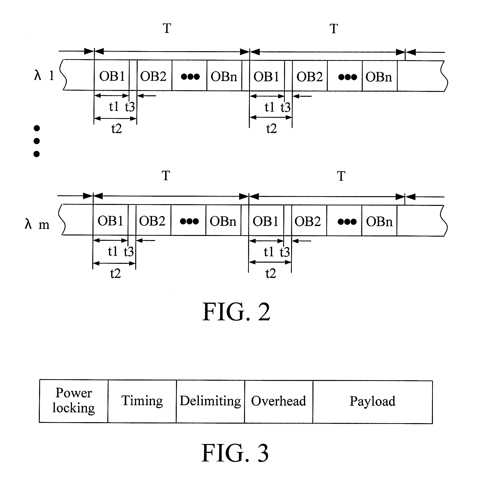
[0061]FIG. 10 is a view of a time sequence relation between a control channel and OB paths according to the present invention. Referring to FIG. 10, the control channel mainly includes an OB frame identifier and a payload, where the OB frame identifier represents a start position of the OB frame. During the synchronization procedure between the OB paths and the control channel, the OB frames of the OB paths need to be aligned with the OB frame identifier in the control channel, for example, the OB frames at λ1 are aligned with the OB frame identifier in the control channel λc.

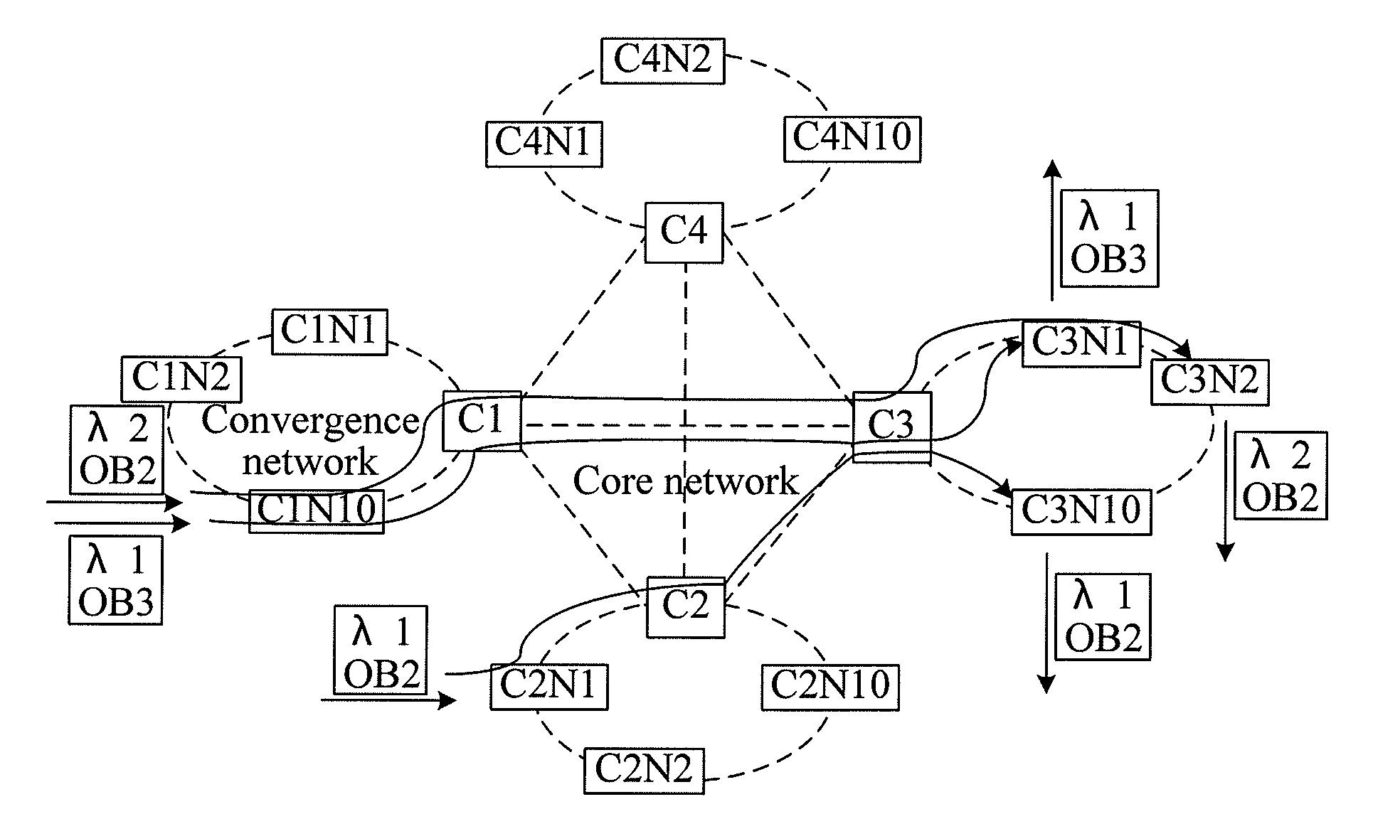
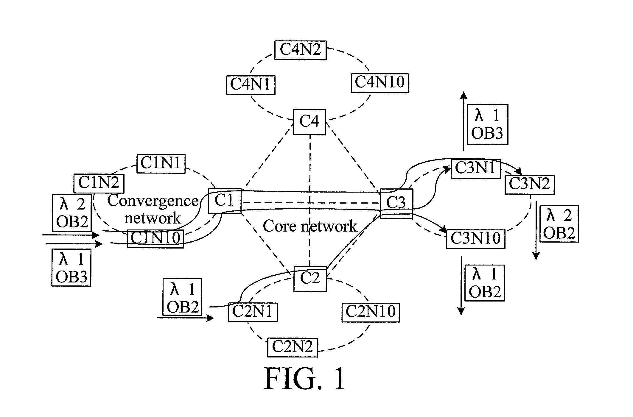
[0062]In addition, all the edge nodes in FIG. 1 may adopt the burst transmitter having the adjustable wavelength and the burst receiver having the fixed wavelength. Here, each edge node receives the OB paths at one fixed wavelength, and this situation is not shown in FIG. 1. A plurality of OB paths bearing the service data among the nodes as shown in FIG. 1 is only adapted to describe a plurality of situations ...


PUM


Abstract

A node, a data processing system, and a data processing method are provided. The node includes a control module, adapted to generate synchronization information and Optical Burst (OB) configuration information; at least one synchronization processing module, adapted to perform a synchronization process on OB paths at a plurality of wavelengths according to the synchronization information; and a cross-connection module, adapted to perform, a cross-connection process on the OB paths, on which the synchronization process has been performed. The data processing system includes at least two nodes, where the nodes are connected through OB paths at one or more wavelengths, and the nodes are adapted to transfer service data through the OB paths. The technical solutions can reduce volume, power consumption, and costs of the nodes, and avoid a problem of generation of data conflict on an optical layer due to lack of optical buffers in all optical switching.

Description

CROSS-REFERENCE TO RELATED APPLICATIONS[0001]This application is a continuation of International Application No. PCT / CN2009 / 072548, filed on Jun. 30, 2009, which claims priority to Chinese Patent Application No. 200810128215.6, filed on Jun. 30, 2008, both of which are hereby incorporated by reference in their entireties.FIELD OF THE TECHNOLOGY[0002]The present invention relates to the field of communications, and more particularly to a node, a data processing system, and a data processing method.BACKGROUND OF THE INVENTION[0003]Nodes in a communications network may be divided into a source node, a destination node, and an intermediate node according to their functions. The source node is a node serving as a source for sending service data, the destination node is a node serving as a sink for receiving the service data, and the intermediate node is a node for forwarding the service data. In other words, the node to which service data is added may be called the source node, and the n...

Claims


Application Information

Patent Timeline
Patent Type & Authority Applications(United States)
IPC IPC(8): H04B10/00
CPCH04J3/0658H04J14/0205H04J14/0212H04J14/0213H04J14/0283H04J14/0284H04Q2011/0064H04L45/62H04Q11/0005H04Q11/0066H04Q11/0071H04Q2011/0045H04J14/0286
Inventor CAO, SHIYI
Owner HUAWEI TECH CO LTD
Why Eureka
Try Eureka