
Method for estimating the position and the speed of a target with a radar emitting an OFDM waveform

a radar and waveform technology, applied in the direction of digital transmission, instruments, measurement devices, etc., can solve the problems of misleading the comprehension of the environment, the inability to detect the presence of targets, and the degradation of the electromagnetic frequency band under us

Active Publication Date: 2014-10-14
THALES NEDERLAND BV
View PDF16 Cites 9 Cited by
  • Summary
  • Abstract
  • Description
  • Claims
  • Application Information

AI Technical Summary

Benefits of technology

This patent is about a method for improving the reliability of a system in the presence of interference. The method involves using a combination of frequency agility and high range resolution processing. By compressing the pulses echoed by the target and removing the apparent random distribution of subcarriers, the method improves the system's ability to handle interference.

Problems solved by technology

In modern radar networks aiming at surveillance applications, the combination of a growing number of features to face up a growing number of needs is the new challenge.
The electromagnetic frequency band under use can be subject to degradation, misleading the comprehension of the environment.
As a consequence, the presence of targets may not be detected.
In a short range radar network for example, the source of this degradation can be either channel imperfections or mutual interferences between neighboring telecom stations.
However, if the carrier frequency changes, the Doppler frequency changes accordingly and the conventional Fourier analysis is no longer adapted to perform the Doppler processing.
However, this article focuses on HRR, it does not even address the issue of frequency agility.
However, this patent does not even address the issue of frequency agility.
This article deals with frequency agility, however it does not address the issue of combining frequency agility with Doppler processing or HRR.

Method used


Image

  • Method for estimating the position and the speed of a target with a radar emitting an OFDM waveform
  • Method for estimating the position and the speed of a target with a radar emitting an OFDM waveform
  • Method for estimating the position and the speed of a target with a radar emitting an OFDM waveform

Examples


Embodiment Construction

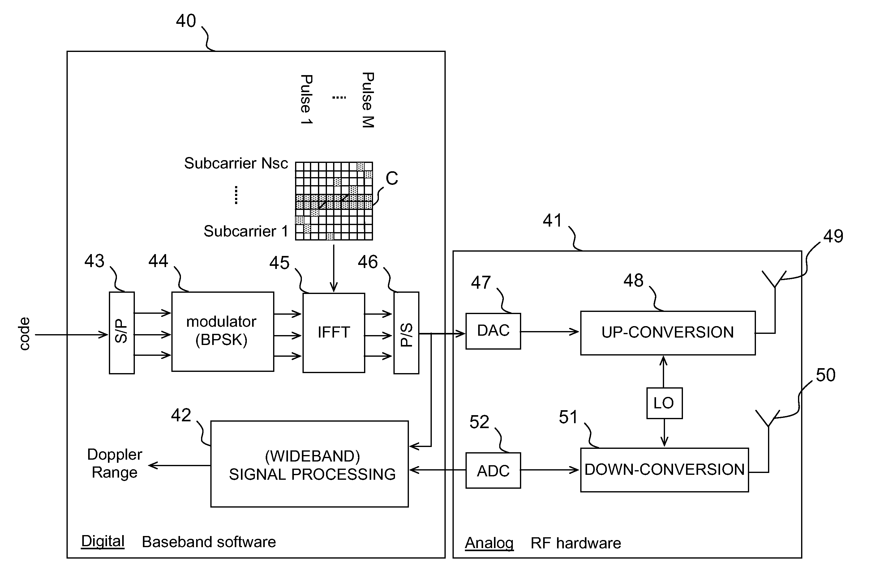
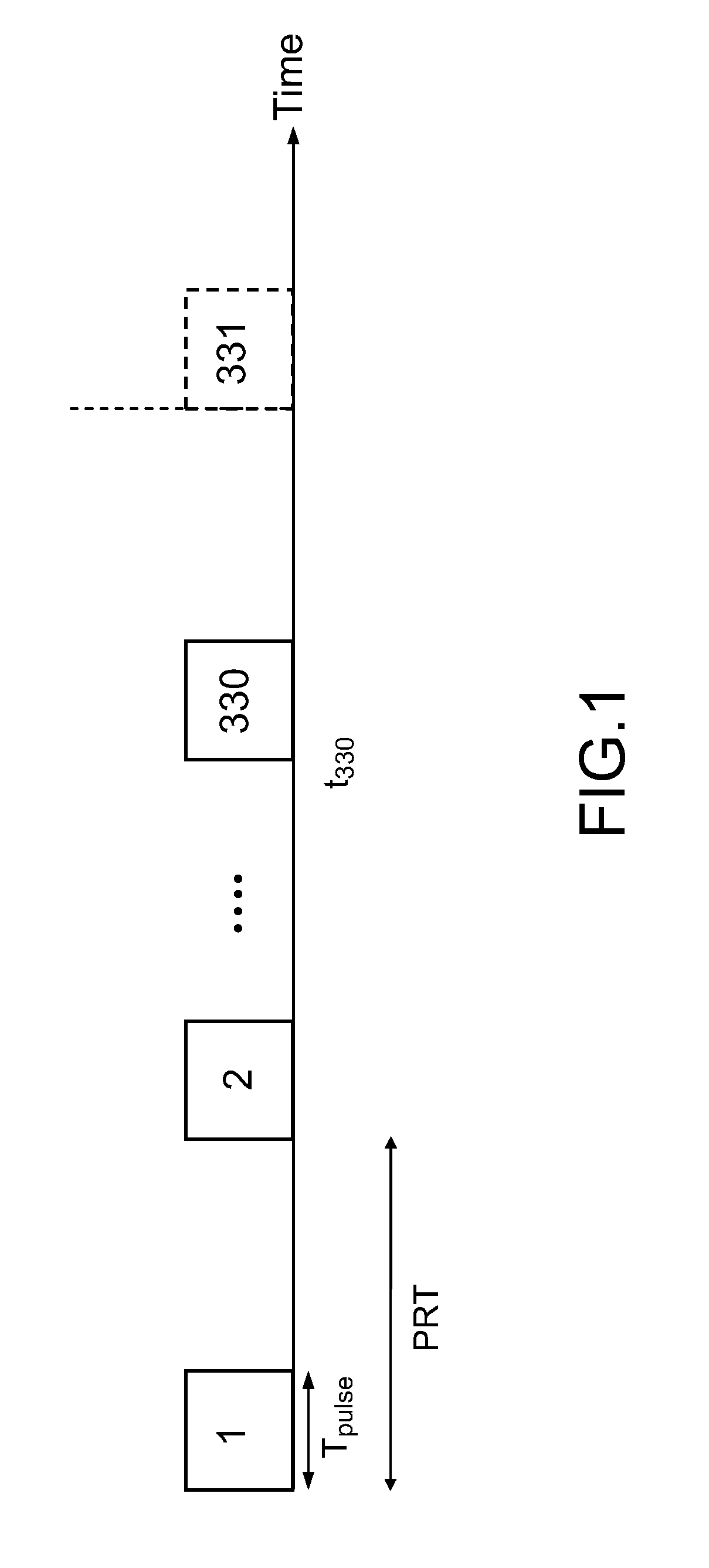
[0040]FIG. 1 schematically illustrates an exemplary waveform specified for a short range radar. The illustrated waveform is a train of 330 pulses, commonly referred to as a “pulse burst”. The pulses of the burst are numbered from 1 to 330. The pulse numbered 331 is the first pulse of the next burst. The invention is exemplified on a waveform designed for short range radar with the background of radar network. The intention is to embed communication messages, for example messages indicating that objects have been detected, into the radar waveform so that information is shared between the various stations. Accordingly, the total bandwidth Bw is much higher than conventional systems, for example Bw may be equal to 300 megahertz (MHz). Needs for high resolution in Doppler suggest a long observation time or a Coherent Processing Interval (CPI). In the illustrated example, the duration Tpulse of each pulse may be equal to 1 microsecond (μs) and the Pulse Repetion Time (PRT) between two co...


PUM


Abstract

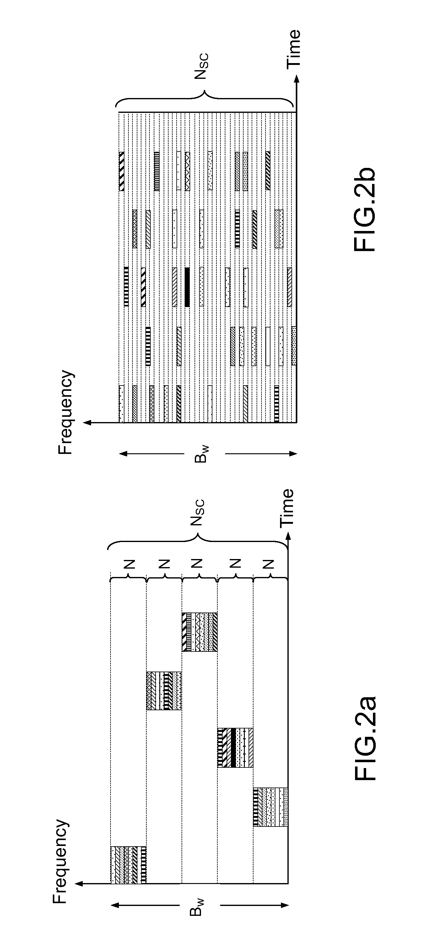
A method for estimating the position and the speed of a target with a radar is provided. The radar emits a waveform including a train of pulses, each pulse having an OFDM chip constructed from subcarriers, the subcarriers covering the whole bandwidth of the radar. Upon receipt of the echoed pulses, some of the subcarriers are used in a step of Doppler processing, each of the subcarriers being fixed over the pulses. Upon receipt of the echoed pulses, other subcarriers, which are not used for Doppler processing, are used in a step of High Range Resolution processing, the subcarriers being randomly distributed over the pulses.

Description

CROSS-REFERENCE TO RELATED APPLICATIONS[0001]This application is a National Stage of International patent application PCT / EP2009 / 056191, filed on May 20, 2009, which claims priority to foreign Netherlands patent application No. NL 1035463, filed on May 23, 2008, and foreign European patent application No. EP 08162594.9, filed on Aug. 19, 2008, the disclosures of which are incorporated by reference in their entirety.FIELD OF THE INVENTION[0002]The present invention relates to a method for estimating the position and the speed of a target with a radar emitting a waveform of the Orthogonal Frequency Division Multiplexing type (OFDM). The invention is applicable to many radar applications.BACKGROUND OF THE INVENTION[0003]In modern radar networks aiming at surveillance applications, the combination of a growing number of features to face up a growing number of needs is the new challenge. The demands for better performances, faster reaction in more complex environments foster this approac...

Claims


Application Information

Patent Timeline
IPC IPC(8): G01S13/58G01S13/08G01S7/00G01S13/02G01S13/24G01S13/28H04L27/26
CPCG01S13/582G01S13/28G01S13/24G01S7/003G01S13/0209H04L27/2601
Inventor LELLOUCH, GABRIELERKOCEVIC-PRIBIC, RADMILA
Owner THALES NEDERLAND BV
Learn More