Windshield wiper apparatus

a wiper and windscreen technology, applied in the direction of vehicle cleaning, couplings, manufacturing tools, etc., can solve the problems of internal stresses in respective workpieces, and affecting the crimping operation. , to achieve the effect of good dimensional stability of the bearing pin, good stress distribution, and increased tolerance zone for crimping operation

Active Publication Date: 2014-10-21
ROBERT BOSCH GMBH
View PDF20 Cites 20 Cited by
  • Summary
  • Abstract
  • Description
  • Claims
  • Application Information

AI Technical Summary

Benefits of technology

[0015]The relief clearance or depression here can be formed in such a manner that an undercut arises in the region of the crimping-induced deformation, in particular in the region of the greatest deformation. The undercut can be selected in such a manner that the bearing pin forms a type of sacrificial geometry in the edge regions of the deformation regions of the tubular support, said sacrificial geometry moving into the depression or relief clearance in the event of excessive crimping forces due to tolerances being exceeded. This results in an increase in the tolerance zone for the crimping operation. From a certain point, it is thus possible, despite crimping forces rising further, to cause an at most slight change in the component geometries, which allows the crimping operation to be formed in a particularly flexible manner.
[0016]In one exemplary embodiment of the present invention, the bearing pin has a cross section with a bone or butterfly shape. This choice of the shape affords particularly good dimensional stability of the bearing pin and ensures a good distribution of stresses and therefore an equalization of the stresses in the bearing pin, even in the event of higher crimping forces. If a stepwise crimping is carried out, it can be observed that the tubular support becomes more angular and cantered from step to step. As a result, a contact angle α between the tubular support and bearing pin becomes ever smaller the steeper the flanks of the tubular support become in the crimping region. If the contact angle moves toward 90°, a normal force applied to the bearing pin by the torsional moment becomes ever smaller. In other words, the choice of steeper flanks of the bearing pin in relation to the tubular support improves the absorption of forces and torques. This interrelationship is achieved particularly readily with the abovementioned bone or butterfly structure of the bearing pin.

Problems solved by technology

However, this may result in the material of the bearing pin being exposed to very large stresses precisely in the region of the crimp of the connection partners, which may result in adverse effects on the structure of the material or even in material fatigue.
A disadvantage of this method is that, due to the plastic deformation of the tubular support, a very great material loading of the bearing pin occurs precisely in the edge regions of the crimping pockets in the bearing pin.
This results in stress peaks which may result in internal stresses in the respective workpieces or even in fatigue of the heavily loaded material of the bearing pin, and possibly even in the edge regions of the crimping pockets breaking off.
However, this is very difficult, since, in the fitted state of the bearing pin and tubular support, the crimping pockets formed on the bearing pin are not visible from the outside.
Since the material of the tubular support is generally steel and therefore requires a higher deformation force than the bearing pin material which is inserted thereon and is generally produced from aluminum, zinc or plastic, it is also not possible to measure a significant increase in force upon deformation of the bearing pin during the crimping operation.
Force-controlled crimping on the basis of the different material behavior is therefore possible only with difficulty, and therefore a pure displacement control has to be used for the crimping operation, which is associated with a further increased risk of introducing stress peaks into the bearing pin, in particular in the event of excessive crimping forces.

Method used


Image

  • Windshield wiper apparatus
  • Windshield wiper apparatus
  • Windshield wiper apparatus

Examples


Embodiment Construction

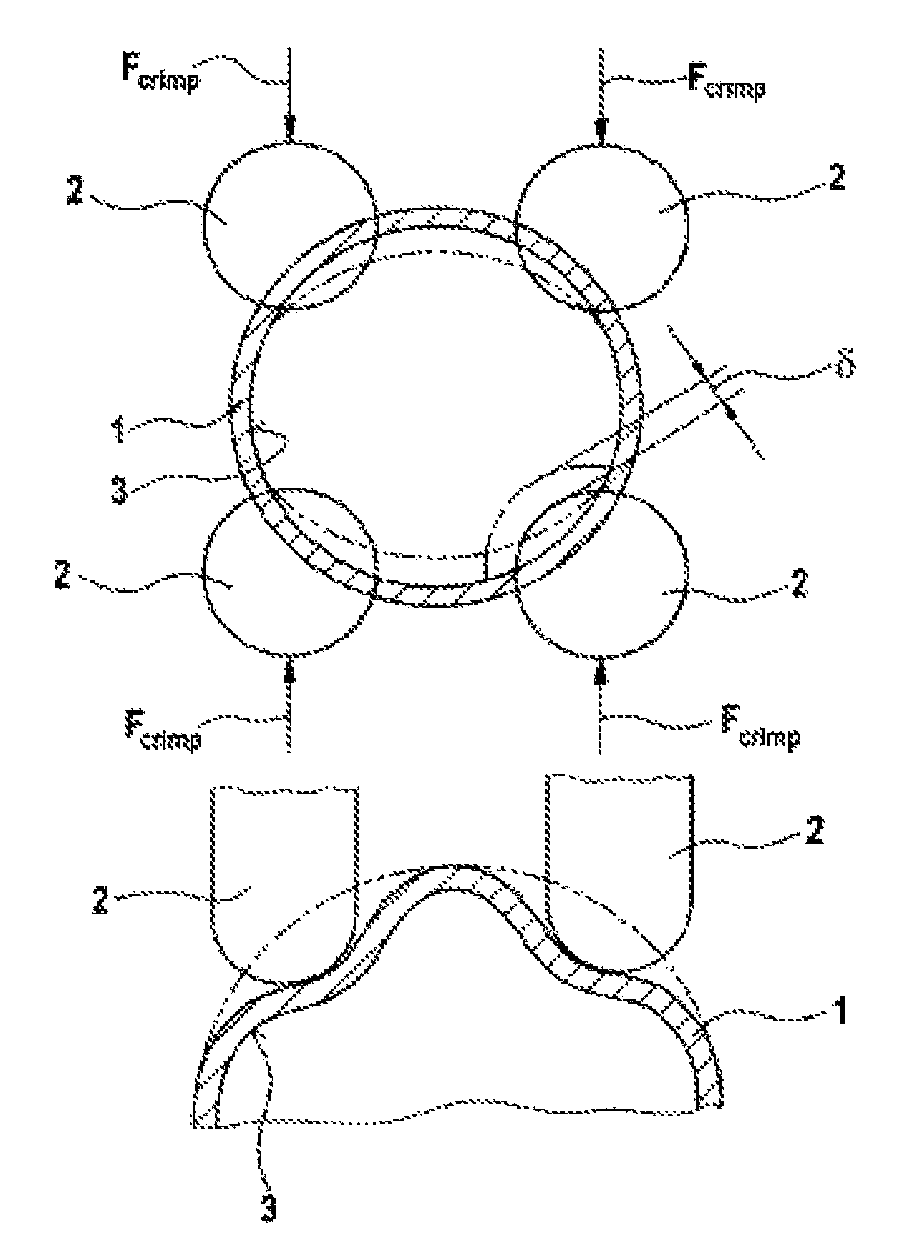
[0037]FIG. 1 shows a schematic cross-sectional illustration of a tubular support 1 of a windshield wiper apparatus (not illustrated specifically) for a motor vehicle.

[0038]A crimping tool which comprises four crimping punches 4 is arranged on the tubular support 1. The crimping punches 2 are arranged in such a manner that a springback is adapted to the crimping-induced deformation of the circular cross section of the tubular support 1, i.e. the springback 6 and the deformation are minimal.

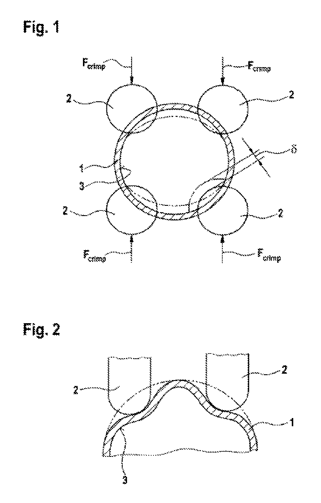
[0039]In its original shape, the tubular support 1 has a circular cross-sectional area with an inner contour 3 which, by application of a force Fcrimp to the crimping punches 2, is deformed in regions such that, after the crimping operation, said inner contour assumes a shape as shown in FIG. 2. According to the prior art, a bearing pin is inserted into the tubular support 1 according to FIGS. 1 and 2, the cross-sectional area of which bearing pin is of substantially circular design and the outer c...


PUM

PropertyMeasurementUnit
contact angleaaaaaaaaaa
stress-optimizedaaaaaaaaaa
deformation forceaaaaaaaaaa

Abstract

The invention relates to a windscreen wiper apparatus for a motor vehicle, having a wiper motor and having at least one wiper bearing in which a wiper shaft is mounted, it being possible to drive said wiper shaft by means of the wiper motor in order to operate a wiper arm which is connected to the wiper shaft, wherein the wiper bearing has a bearing pin (4) for holding a tubular support (1), it being possible for said bearing pin to be fixed to the tubular support (1) by means of a crimp, characterized in that the bearing pin (4) has an outer contour (5) which is already formed, at least in a region of overlap with the crimp, so as to correspond to an inner contour (3) of the crimped tubular support (1), before the crimp is introduced, and also to a method for producing said windscreen wiper apparatus.

Description

BACKGROUND OF THE INVENTION[0001]The present invention relates to a windshield wiper apparatus for a motor vehicle, with a wiper motor and with at least one wiper bearing in which a wiper shaft is mounted, the wiper shaft being drivable by means of the wiper motor in order to actuate a wiper arm connected to the wiper shaft, wherein the wiper bearing has a bearing pin for receiving a tubular support, said bearing pin being fixable to the tubular support by means of a crimp, and to a method for the production of said windshield wiper apparatus.[0002]Windshield wiper apparatuses of this type are known in general. During the crimping operation, the components to be fixed to one another are exposed to a very large deformation force in order to produce an interlocking connection between the bearing pin and the tubular support. In the process, in addition to the tubular support, regions of the material of the bearing pin are also plastically deformed in order to obtain an appropriately in...

Claims


Application Information

Patent Timeline
Patent Type & Authority Patents(United States)
IPC IPC(8): B60S1/04B60S1/06
CPCB60S1/0425Y10T29/49927Y10T403/49Y10T29/4978Y10T29/49771Y10T29/49925Y10T29/49913Y10T29/49929B60S1/02B60S1/0436B60S1/34
Inventor WEILER, MICHAELKRAUS, ACHIMMAI, STEFANHAUSER, FLORIAN
Owner ROBERT BOSCH GMBH
Why Eureka
Try Eureka