Card feed unit, read out unit, ATM and method

Inactive Publication Date: 2014-10-28
CARD SWIPE PROTECTION TECH
View PDF13 Cites 2 Cited by
  • Summary
  • Abstract
  • Description
  • Claims
  • Application Information

AI Technical Summary

Benefits of technology

[0034]Preferably, the receipt member comprises an end part closing end of the channel that preferably provides an L-shaped ending to the receipt channel. This part of the L-shaped ending is partly responsible for indicating to the user how to card is to be inserted into the receipt position. Furthermore, this L-shaped ending is responsible for presenting a longitudinal movement of the card into the channel, thereby effectively preventing the possibilities for skimming by means of bringing a reading head off a skimmer into end of the channel. The data carrier would simply not reach th

Problems solved by technology

The results thereof is that during this operation, the data carrier cannot be read out by a reading

Method used


Image

  • Card feed unit, read out unit, ATM and method
  • Card feed unit, read out unit, ATM and method
  • Card feed unit, read out unit, ATM and method

Examples


first embodiment

[0083]FIG. 9 are block diagrams illustrating a first embodiment according to the invention. Reference numeral 204 indicates a direction wherein card 106 is being moved by the user to insert card 106 into receiving section 108. In this embodiment, receiving section 108 has a slot having a width W that is large enough for card 106 to pass through, longer end first. That is, the dimension of the slot allows inserting card 106 with strip 110 remaining parallel to the slot. In the invention, direction 204 differs substantially from the direction 116 of strip 110. Receiving section 108 may be provided with a profiled entrance for properly guiding card 106 during insertion and / or removal. In FIG. 9A, the user moves card 106 towards receiving section 108 in direction 204.

[0084]In FIG. 9B card 106 has been moved to such a position that strip 110 is obscured by receiving section 108. Note that there is not a single location, stationary with respect to receiving section 108, where a reading he...

second embodiment

[0089]FIGS. 10 A and B are block diagrams illustrating a further example of such a Receiving section 108 in this example comprises an arm 502 mounted on, and extending from, user interface 108. Arm 502 has a channel along at least part of its length. Card 106 can be inserted into this channel in the direction indicated by arrow 504. Note that the direction of arrow 504 is substantially perpendicular to the direction of magnetic strip 110. The depth of the channel is chosen so as to have arm 502 obscure strip 110 when card 106 has been inserted. After card 106 has thus been inserted into the channel, the user moves card 106 in the direction of an arrow 602 in order to insert card 106 into the slot of known apparatus.

[0090]As a result, the path traversed by strip 110 when moved in direction 602 lies entirely within reading area 90. In order to remove card 106, card 106 is slid back in a direction opposite to direction 602, and taken out of arm 502 in a direction opposite to direction...

embodiment 1100

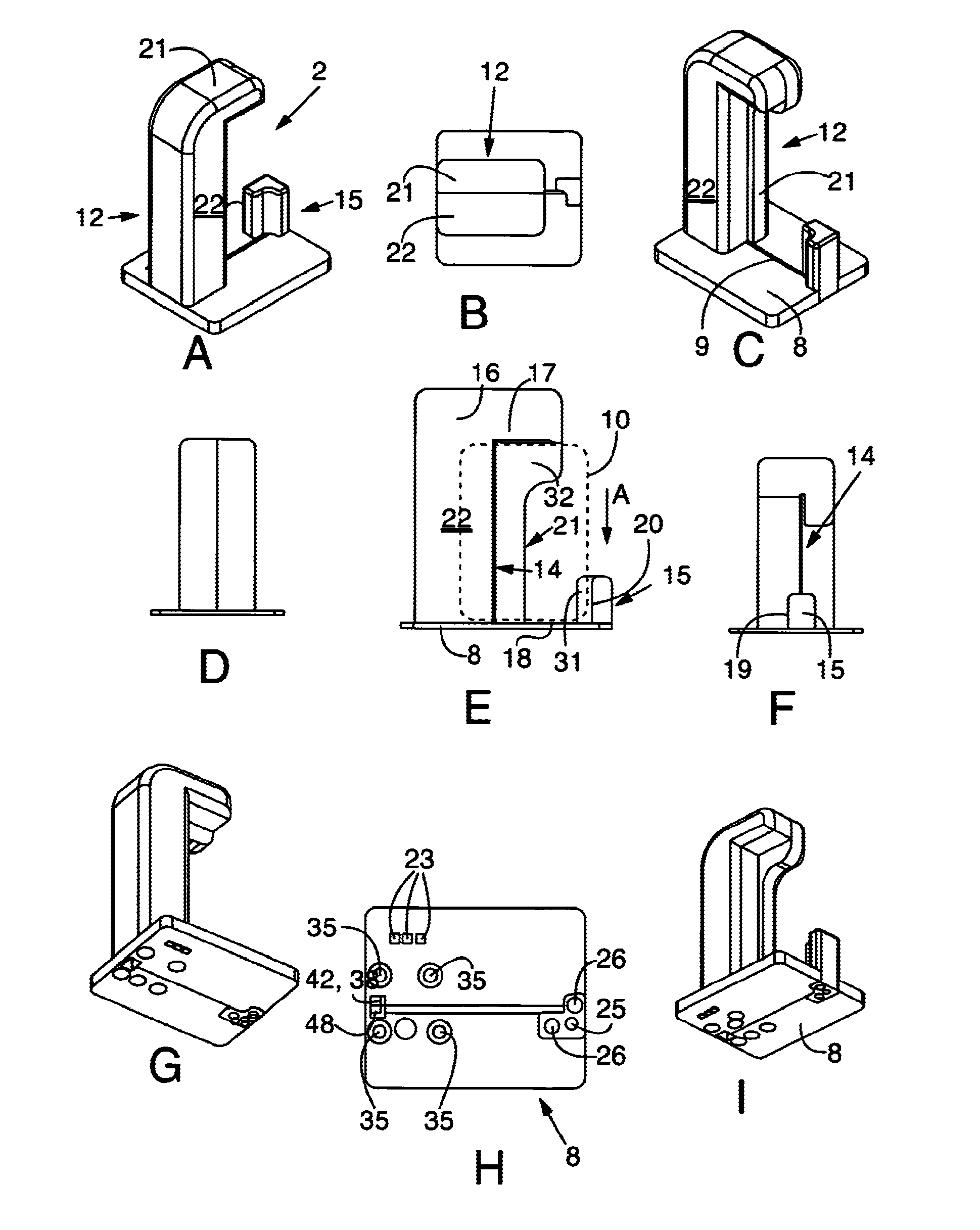
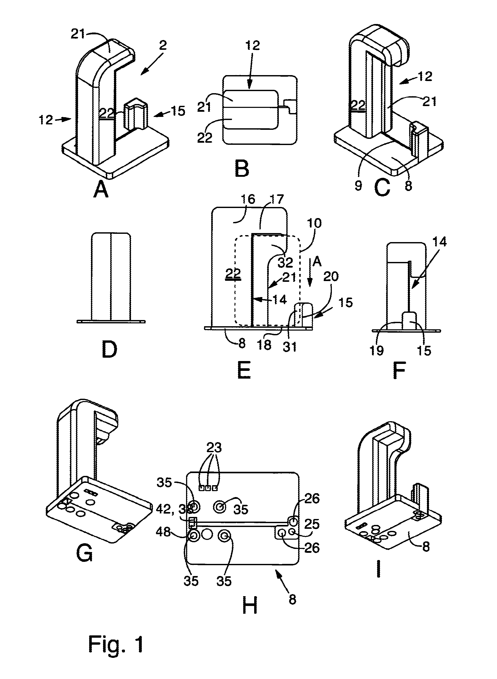
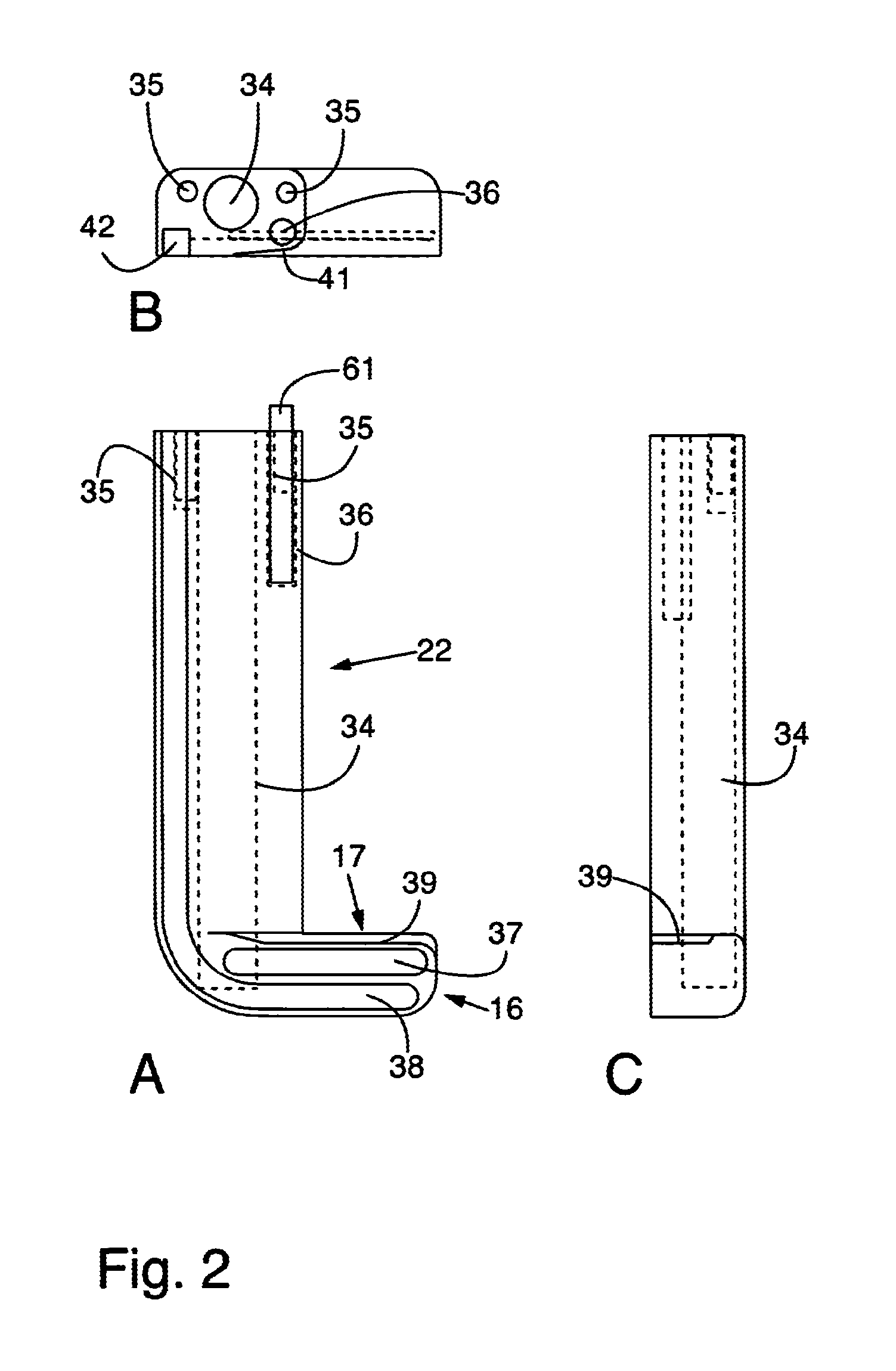
[0095]Furthermore, the wires or strips are arranged close to the drain, so that they will be affected if someone tries to increase the interior diameter of the drain with a file or with a drill. FIGS. 11, 12, 13 and 14 illustrate an example of a further embodiment 1100 of the invention, in a longitudinal cross-section, applicable to swipe card readers. As known, a conventional swipe card reader enables the user to swipe card 106 along an open channel past a reading head. Card 106 is entered into the channel at one open end, swept past the reading head mounted in the channel, and taken out of the channel at the other open end, all in one run. It is fairly easy to put a skimming reading head at or in the channel near one or near both of the ends. The invention provides anti-skimming measures for swipe readers as follows, based on the general theme of the invention as discussed above.

[0096]Embodiment 1100 has a receiving section 108 with an elongated portion 1102 having a channel 1104....


PUM


Abstract

The present invention relates to a card feed unit for transferring a data carrier of card information of a multi-services cards, such as a bank card or credit card, to a reading head of a reading unit for at least reading out of card information, the card feed unit comprising: attachment means for attaching the card feed unit in an arrangement respective of the reading head that is suitable for transporting the data carrier of the card in the direction of the meeting head, a receipt position for receipt of the card, a transfer assembly for transferring the card by means of the transfer assembly in the direction of the reading head, in which: the card feed unit is suitable for, during insertion of the card in the receipt position, receiving the card in the receipt position by means of an insertion operation with a direction of movement that, at least as seen in one direction, is substantially perpendicular to the readout direction of the card for preventing that the card is readable during the insertion operation.

Description

BACKGROUND OF THE INVENTION[0001]The present invention relates to a card feed unit for safely performing card feed operations for feeding a card into automated transactions machines. The present invention also relates to a read out unit comprising a card feed unit. The present invention also relates to a transaction machine, such as a payment machine or a cash drawing machine ATM, comprising a card feed unit. The present invention also relates to a method for safely performing of transactions while applying a card feed unit and or a machine.[0002]Within the scope of this text, the following definitions apply.[0003]Card information is intended to mean information storable in a data carrier to be read by the card reader, such as for performing card transactions.[0004]A direction substantially perpendicular to the reading direction of the card means that the direction is substantially excluding a direction running parallel to the reading direction of a card. Therefore, the direction su...

Claims


Application Information

Patent Timeline
IPC IPC(8): G06K13/08G06K7/08
CPCG06K13/0843G07F19/2055
Inventor VAN DEN BOGART, LEONARDUS ANTONIUS MARIAGOEDEE, CORNELIS JOHANNESDE JONGH, MARINA HELENA
Owner CARD SWIPE PROTECTION TECH
Why Eureka
Try Eureka