Trigger joint

a technology of trigger joint and riser, which is applied in the direction of screw threaded joint, wellbore/well accessories, sealing/packing, etc., can solve the problems of increasing the time to release, the riser will no longer be floating, and the emergency quick disconnect (eqd) may take more time than is available, so as to increase the tension in the riser and increase the available time to release

Active Publication Date: 2014-11-04
FMC KONGSBERG SUS
View PDF17 Cites 21 Cited by
  • Summary
  • Abstract
  • Description
  • Claims
  • Application Information

AI Technical Summary

Benefits of technology

[0023]The invention also regards a method for increasing the operation window of a riser extending between a floating installation and a fixed subsea installation. The method comprises providing a joint as described above between the floating installation and an EQDP, preferably close to the EQDP, and when the floating installation deviates from its operational area and thereby increases the tension in the riser above a threshold value, the outflow of fluid from the one chamber part is controlled and thereby controls the extension rate of the joint, thereby increasing the available time to release the EQDP.

Problems solved by technology

However, there are emergency situations where the floating installation will no longer be within such a safe operation window or is in the process of leaving such a safe operation window.
The problem is to have enough time for the execution of an emergency disconnect in the event of an emergency situation.
In a drift off / drive off situation of the floating installation, or if the heave compensator fails, there is normally very little time available to disconnect the riser from the wellhead.
It has been found that activation of the Emergency Quick Disconnect (EQD) may take more time than is available.

Method used


Image

  • Trigger joint
  • Trigger joint
  • Trigger joint

Examples


first embodiment

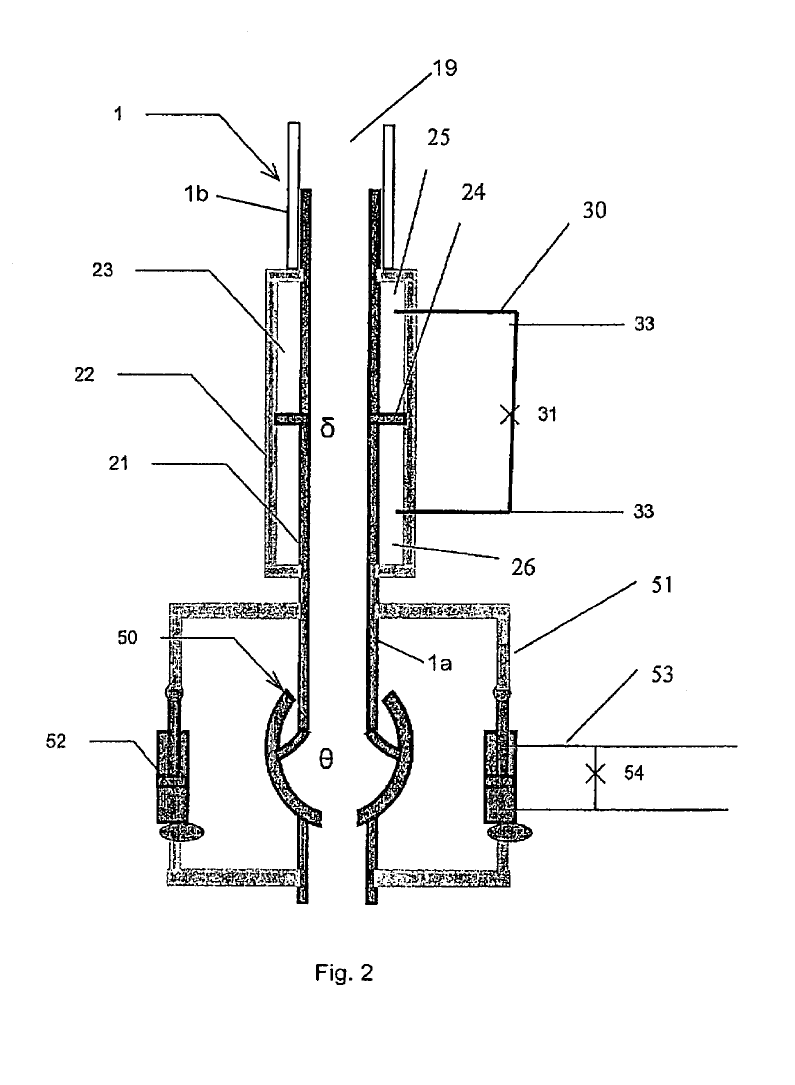
[0034]In FIG. 2 a joint is shown as a schematic cross section. The joint comprises an inner pipe segment 21 and an outer pipe segment 22. These pipe segments 21, 22 may move relative to each other in an axial direction of the pipe segments when the joint is activated. The inner pipe segment 21 is moved relatively out of the outer pipe segment 22, thereby extending the length of the joint. The inner pipe segment 21 is at one end configured to be attached to a lower riser segment 1a extending below the joint. The outer pipe segment 22 is also at one end, positioned on an opposite side of the joint, configured to be connected to an upper riser segment 1b extending above the joint. An inner passage through the two pipe segments 21, 22 will in a connected state form a continuing passage with the internal passage 19 in the riser. This inner passage through the pipe segments 21, 22 may be in line with the passage in the riser. The inner and outer pipe segments 21, 22 are configured such th...

second embodiment

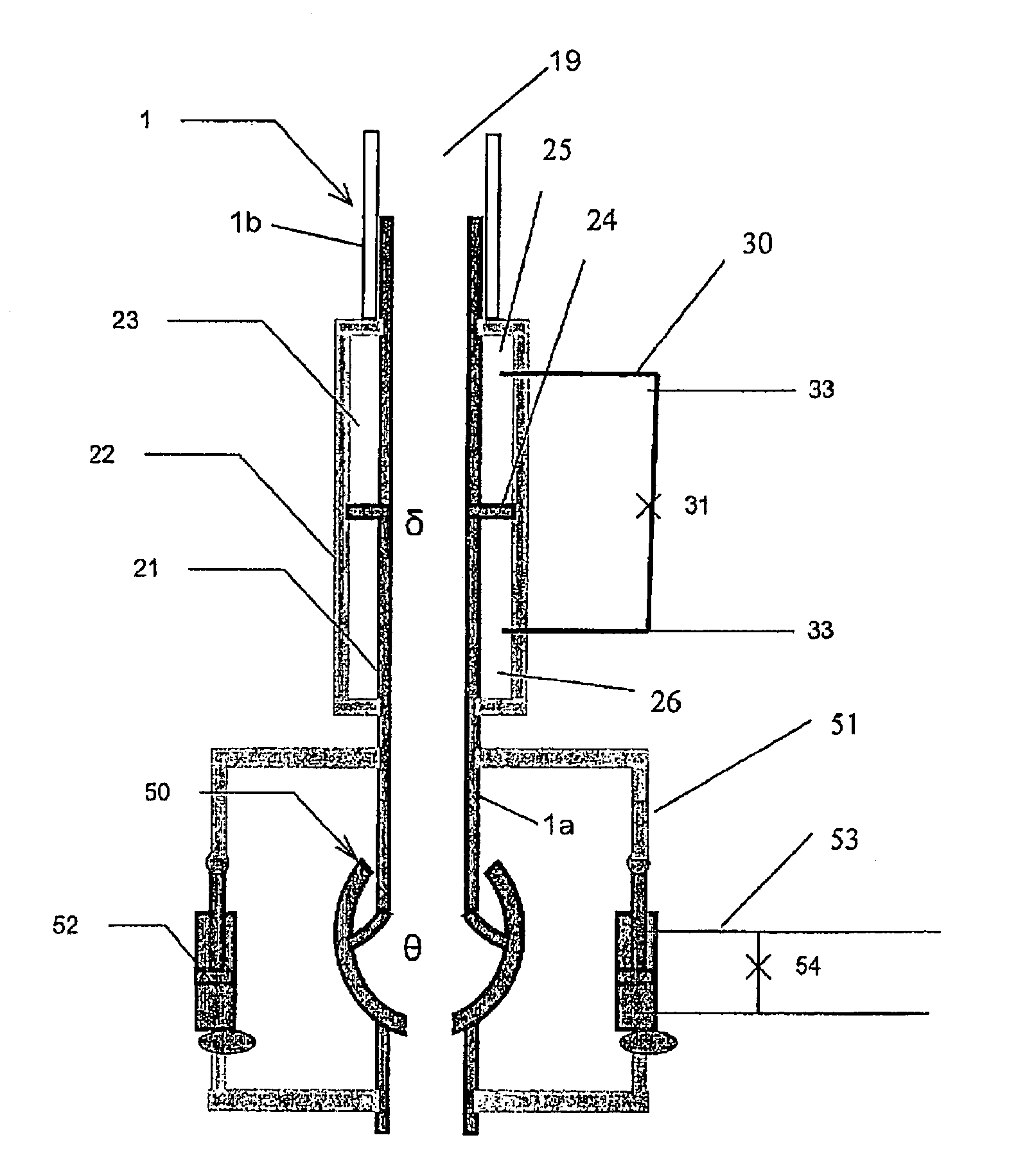
[0038]In FIG. 3 there is also shown a cross section of the joint. In this embodiment the fluid line connection 30 between the two chamber parts formed by the piston 24 between the inner pipe segment 21 and the outer pipe segment 22 comprises a valve 32. As indicated, this valve 32 may be controlled by a control module 34, which operates the valve in response to signals received from a sensor 33 reading the tension in the riser. Possibly the sensors 33b, 33c in the flex joint 50 may also provide information about the angular stress in the riser to the control module for input in the operation of the valve. The control module 34 may also be linked to the valve 55 in the flex joint. The control module may also control the operation of the valve 55 in the flex joint. As one may see from this embodiment the inner and outer pipe segments 21, 22 are formed such that they allow extension in the joint by, for instance, having an extension of the inner pipe segment 21 on the opposite side of ...

third embodiment

[0039]In FIG. 4 there is shown the joint. Only the different features from the previous embodiment will be described. In this embodiment the valve 32 in the fluid line connection 30 between the two chamber parts formed between the inner and outer pipe segments 21, 22 is mechanically operated. A fluid line 35a extends from one chamber part to one side of a piston 37a arranged in a cylinder 38a of a first cylinder arrangement 36a. The piston 37a is connected to a piston rod 39a. This piston rod 39a is attached to a lever arm 40 which is allowed to move relative a fulcrum 41. An increased pressure in the fluid within the chamber part will be transferred to the piston arrangement 36a, and there try to move the piston 37a with the piston rod 39a to rotate the lever arm 40 about the fulcrum 41. There is in this embodiment arranged a spring element 42 acting in the opposite direction of the pressure in the chamber part on the lever arm. The pressure in the chamber part must therefore be so...


PUM


Abstract

The present invention regards a joint for use in a riser (1) extending between a floating installation (3) and a subsea installation (2). The joint comprises an inner pipe segment (21) and an outer pipe segments (22), arranged moveable relative each other in an axial direction and connectable to respective riser segments, forming a chamber (23) between them with a radially extending piston (24), dividing the chamber (23) in a first chamber part (25) and a second chamber part (26), wherein on of said chamber parts (25) in an initial position of the joint is adapted to contain a mainly incompressible fluid, this chamber part (25) decreasing in volume as the inner pipe segment (21) is moved relatively out of the outer pipe segment (22). According to the invention the joint is configured with a fluid line connection (30) from said one chamber part (25) to the other chamber part (26), configured such that the relative movement of the pipe segments (21, 22) is controlled by the allowed flow rate of a fluid flowing out of the chamber part (25) through the fluid line connection (30) to the other chamber part (26).

Description

[0001]The present invention regards a joint for use in a riser and a method for extending an operation window for a riser.BACKGROUND OF THE INVENTION[0002]A riser is a pipe extending between a subsea installation and a floating installation for transferring fluids and or signals between equipment at the two installations. There may be produced hydrocarbons, drilling fluids, injection fluids, etc. transferred by the riser. The floating installation which will move due to changing weather conditions, wind waves, currents, etc. is normally given a safe operation window. Such a safe operation window may for instance define an area wherein the installation may move without danger of damaging the equipment, wind conditions where the installation can be kept within this area, etc. However, there are emergency situations where the floating installation will no longer be within such a safe operation window or is in the process of leaving such a safe operation window. These are normally refer...

Claims


Application Information

Patent Timeline
Patent Type & Authority Patents(United States)
IPC IPC(8): E21B19/09E21B17/08E21B17/07E21B17/02E21B19/00
CPCE21B17/085E21B19/006
Inventor CARLSEN, HANS-PAULCARLSEN, TOR-OYSTEINJOHANSEN, JOHN A.
Owner FMC KONGSBERG SUS
Why Eureka
Try Eureka