Rotary cutter

a rotary cutter and cutter body technology, applied in the field of rotary cutters, can solve the problems of narrow application range, large centrifugal force effect on the fluid flowing inside the flow path, and inability to spray mist well

Active Publication Date: 2014-11-04
SUBARU CORP
View PDF39 Cites 3 Cited by
  • Summary
  • Abstract
  • Description
  • Claims
  • Application Information

AI Technical Summary

Benefits of technology

[0046]a nut that engages with the gripping piece, threadably mounts on the holder and makes tightening possible by pressing the outer taper of the gripping piece toward the inner taper of the holder; and
[0053]With the present invention, due to intermittent connection between a first supply path and a second supply path, a mixture of cutting fluid and air that is fed from a supply pipe is concentrated and fed to the second supply path for a specified connection period without the internal pressure dropping, then is sprayed as is toward a throttle without being overcome by centrifugal force and without colliding into the inner wall that is separated from the throttle, and thus, being kept from returning to a liquid form, the mixture smoothly and quickly reaches the throttle that is located on the axis of rotation.
[0054]Even when the change of the cutting fluid to a mist form in the front throttle chamber is not adequate, the action of the throttle sufficiently changes the cutting fluid to a mist form, after which, by passing and feeding the cutting fluid though a rear throttle chamber, which is concentratedly located on or near the axis of rotation, and through a third supply path, the invention has the advantage of being able to spray cutting fluid in a mist form from the tip end section of a rotary cutting tool while keeping the cutting fluid from returning to a liquid form due to centrifugal force.
[0055]Moreover, with the present invention, the front throttle chamber is formed such that the diameter thereof expands from the second supply path, and the throttle is formed such that the diameter is less than the minimum diameter of the second supply path, and the front throttle chamber is formed such that the capacity thereof is greater than that of the rear throttle chamber. Therefore, during the period that the first supply path and second supply path are connected, pressurized cutting fluid and air builds up in the front throttle chamber, and the front throttle chamber reaches a maximum pressure. The pressurized cutting fluid and air that is built up in the front throttle chamber is gradually fed from the throttle, and even when the first supply path and second supply path are disconnected, the internal pressure in the front throttle chamber is kept from dropping suddenly, and drops relatively smoothly. Before the drop in internal pressure becomes to extreme, the next connection period between the first supply path and second supply path begins, and the front throttle chamber returns to the maximum pressure by a relatively small rise in pressure. As a result, there is an effect of suppressing pulsation of the spray from the tip end section of the rotary cutting tool, and thus it is possible to stably spray cutting fluid in a mist form from the tip end of the rotary cutting tool. In other words, providing a throttle, and providing a front throttle chamber that has a relatively large surface area and large volume, has an effect of easing pulsating change.
[0060]By doing this, it is possible to suitably maintain a connection period between the first supply path and second supply path, smoothly introduce the fluid-air mixture that is fed from the supply pipe to the second supply path, and forcefully spray the fluid-air mixture toward the throttle while keeping the mixture from returning to a liquid state without the pressure dropping.

Problems solved by technology

However, a center-type supply path is limited to mechanical construction having a path that penetrates completely through the center of rotation, making the range of application narrow.
In addition, a supply path that is separated from the center of rotation also has the disadvantage in that the effect of centrifugal force on the fluid flowing inside the flow path is relatively large.
However, in order to supply a combination of cutting fluid and air in the form of a mist in a conventional rotary cutter having a peripheral-type supply path, there are the following problems.
In a convention rotary cutter having a peripheral-type supply path, even though a combination of cutting oil and air in the form of a mist is supplied from around the principal rotating shaft, mist is not sprayed well from a spray orifice that is provided on the tip end section of the rotary cutting tool, with part sometimes being output in liquid form, or mist is sprayed intermittently or in a pulse-like manner, making it difficult to spray mist stably and steadily.
Moreover, due to that effect, it is difficult to reduce the diameter of the supply path inside the rotary cutting tool, and thus it is difficult to apply this type of supply path to small diameter rotary cutting tools.
The reason that the mist spray become unstable is that mist that is supplied from the perimeter of the main rotating shaft returns to a liquid form when it comes in contact with the inner wall of the supply path due to centrifugal force, and cutting fluid that builds up inside the supply path after returning to a liquid form affects the flow of the cutting fluid in mist form so the output of mist becomes intermittent and pulse-like, causing an unstable mist spray.
Even by increasing the supply pressure of the mist in order to overcome the effect of the centrifugal force, mist still returns to the liquid form when the mist comes in contact with the inner wall of a bent or curved portion of the supply path, so it is difficult to avoid the same result.

Method used


Image

  • Rotary cutter
  • Rotary cutter
  • Rotary cutter

Examples


Embodiment Construction

[0068]In the following, one embodiment of the present invention will be explained with reference to the accompanying drawings. The following is only one embodiment of the present invention, and does not limit the invention.

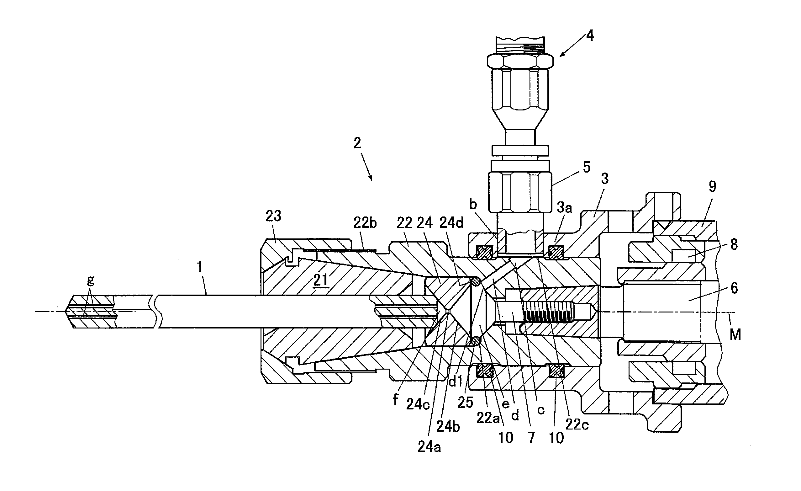
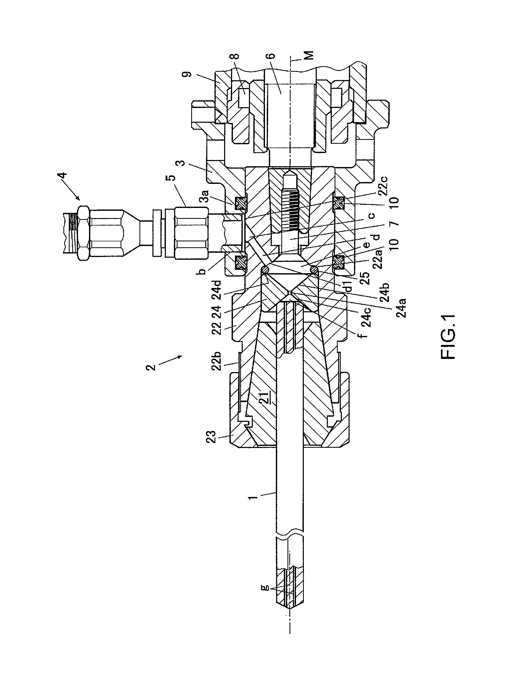
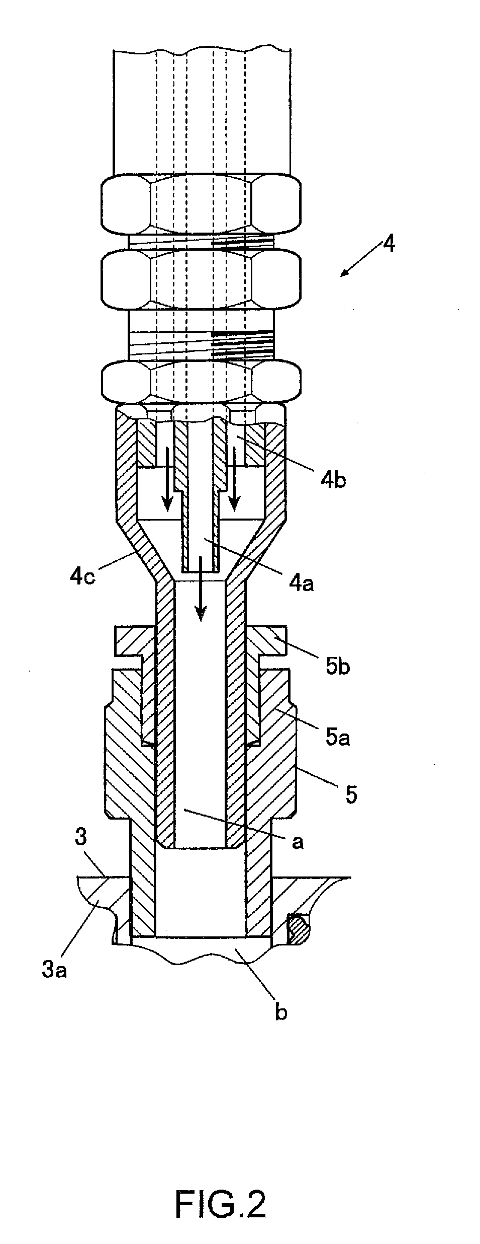
[0069]As illustrated in FIG. 1, FIG. 2 and FIG. 3, the rotary cutter of one embodiment of the present invention comprises a drill 1, a chuck 2, a cover 3, a supply pipe 4 and a connector 5 as a rotary cutting tool.

[0070]The chuck 2 is a collet chuck and comprises a collet 21, a collet holder 22, a collet nut 23, a throttle piece 24 and an O-ring 25.

[0071]The chuck 2 grips and holds the drill 1.

[0072]The collet holder 22 has a cylindrical shape with tapered surfaces on both ends such that the rear end of the collet holder 22 threadably mounts on the main rotating shaft 6, and the collet holder 22 and main rotating shaft 6 are fastened together by a flush bolt 4. This covers the opening on the rear end of the collet holder 22.

[0073]To further assemble, after the fas...


PUM

PropertyMeasurementUnit
opening angle 4θaaaaaaaaaa
opening angleaaaaaaaaaa
air pressureaaaaaaaaaa

Abstract

The object of the invention is to stably spray cutting fluid in a good mist form, when cutting fluid and air are supplied from the surrounding area and cutting fluid is sprayed in a mist form from the tip end section of a rotary cutting tool. The rotary cutter of the present invention sequentially feeds a mixture of cutting fluid and air through a supply pipe 4, first supply path b in a cover 3, second supply paths c, d in a chuck 2, a hollow center cavity (front throttle chamber d, throttle 24a, and rear throttle chamber e) in the chuck, and a third supply path g in a rotary cutting tool 1. The first supply path and second supply path are intermittently connected when the respective openings thereof face each other as the cover and chuck turn relative to each other; the second supply path sprays fluid toward the throttle; the front throttle chamber is formed such the diameter thereof expands from the second supply path; the throttle is formed such that the diameter thereof is less than the smallest diameter of the second supply path; the rear throttle chamber is formed by the rear end surface of the rotary cutting tool and the inner conical surface on the down-flow side of the throttle when that rear end surface and inner conical surface on the down-flow side come in close contact with each other; and the front throttle chamber is formed such that the capacity thereof is greater than that of the rear throttle chamber.

Description

CROSS REFERENCE TO RELATED APPLICATIONS[0001]This application claims priority under 35 U.S.C. 119 based upon Japanese Patent Application No. 2009-218392, filed on Sep. 24, 2009. The entire disclosure of the aforesaid application is incorporated herein by reference.FIELD OF THE INVENTION[0002]The present invention relates to a rotary cutter that sprays a mist comprising a cutting fluid and air from the tip end section of a rotary cutting tool such as a drill.BACKGROUND OF THE INVENTION[0003]Conventionally, cutting fluid such as cutting oil or water soluble coolant has been supplied to the cutting portion (cutting blade or cut material) in order to lubricate and cool the cutting portion in a rotary cutting process. Supplying cutting fluid to the cutting portion has been performed by an external supply method in which cutting fluid is supplied from outside the rotary cutting tool, as well as by an internal supply method in which cutting fluid is supplied from a hole that is formed in t...

Claims


Application Information

Patent Timeline
Patent Type & Authority Patents(United States)
IPC IPC(8): B23Q11/10B23B51/06B23B31/20
CPCB23Q11/1023B23Q11/103B23B2231/24B23B31/20B23B2250/12Y10T279/17111Y10T408/455Y10T409/304032B23B31/20125
Inventor SAITO, MANABUNAKAHATA, TATSUOTAKAHASHI, HIDEHARU
Owner SUBARU CORP
Why Eureka
Try Eureka