Displacement pump with internal compression

a technology of displacement pump and displacement pump, which is applied in the direction of engine lubrication, rotary or oscillating piston engine, rotary piston engine, etc., can solve the problems of not meeting the requirements of reliability, ruggedness, low price level, compressor efficiency, etc., and achieves the effect of facilitating axial mobility and ensuring the function of floating bearing

Inactive Publication Date: 2014-11-04
STEFFENS RALF
View PDF8 Cites 2 Cited by
  • Summary
  • Abstract
  • Description
  • Claims
  • Application Information

AI Technical Summary

Benefits of technology

[0006]The object of the invention lies in improving the efficiency of dry-compressing dual-shaft rotary displacement machines for the compression and delivery of gaseous delivery media, and to reduce the expenditures also for higher compression pressures, as well as to significantly reduce the stresses due to the gas forces in the axial and radial direction.

Problems solved by technology

However, what these machines have in common is that they still do not meet today's requirements relating to reliability, ruggedness, constructional size and weight, while at the same time having a low price level and satisfactory compressor efficiency.
For achieving greater compressor powers however, there is still no efficient and inexpensive solution to minimize the pump-specific forces in the axial and radial direction and minimize the compressor power values efficiently, reliably, robustly and inexpensively.
Until now, dry-compressing screw compressors having two screw compressors with an intermediate gas cooling system still must be used for higher pressure values, for example, 11 bar as absolute pressure, with an unsatisfactory efficiency at the same time.

Method used


Image

  • Displacement pump with internal compression
  • Displacement pump with internal compression
  • Displacement pump with internal compression

Examples


Embodiment Construction

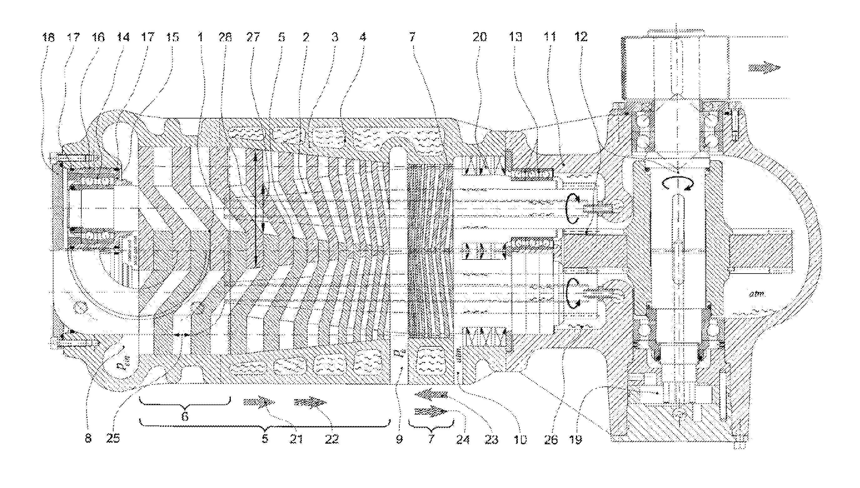
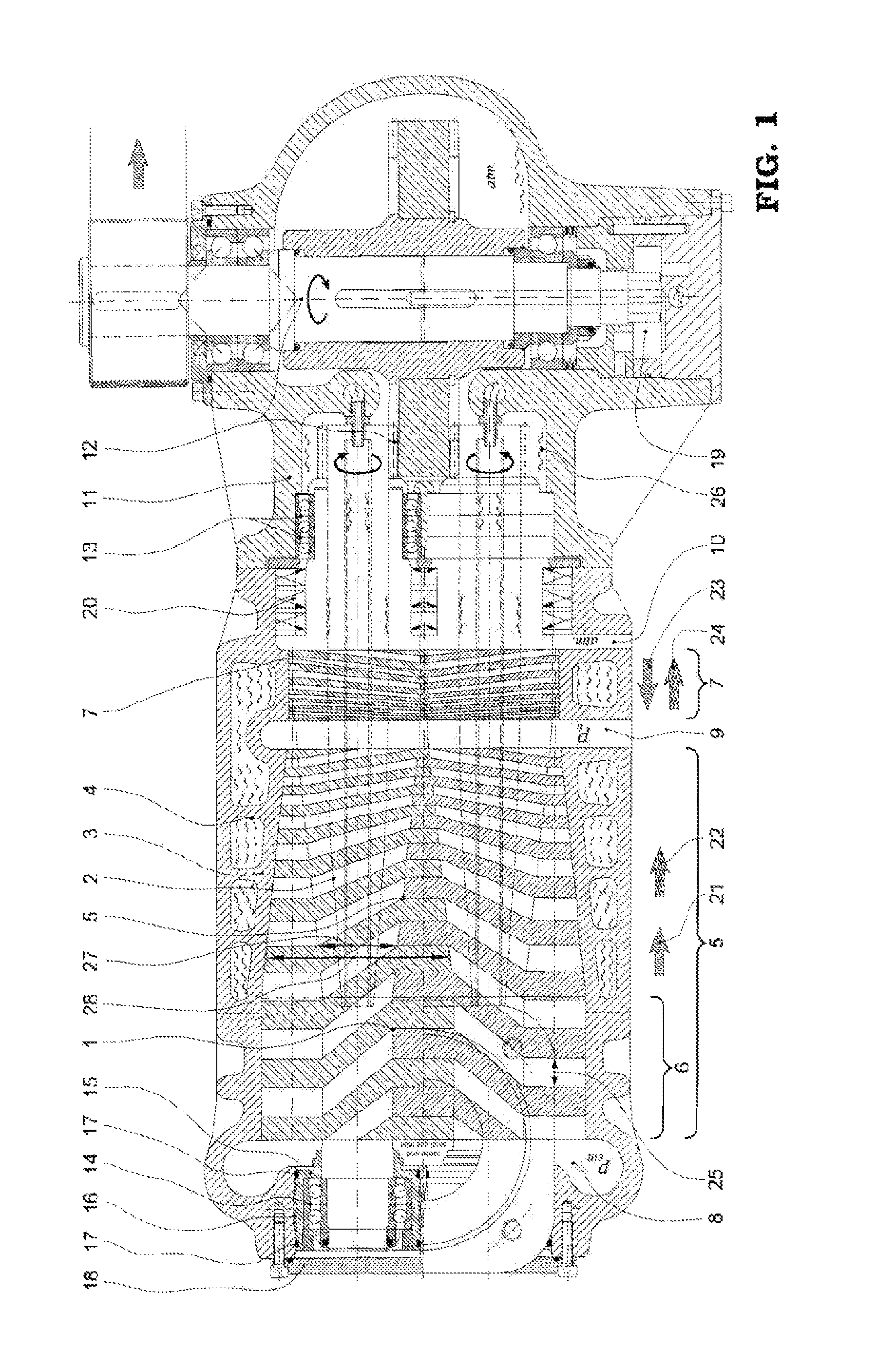
[0044]FIG. 1 shows an embodiment in a sectional view through the entire screw spindle pump. The minor-identical rotor pair (1) rotates in a pump housing (3) with a gas inlet (8) and a gas outlet collector space (9). The rotor pair is driven by a crown or bevel gear (12) with a drive shaft in such a way that the displacement rotors rotate in opposite directions and without contact in the pump working space. The driving motor is not shown separately.

[0045]Each screw spindle rotor is retained, on the gas inlet side, in rolling bearings (14) that are provided with lifetime grease-lubrication as a floating bearing arrangement and, on the drive side, in oil-lubricated rolling bearings (13) as a locating bearing arrangement for securing the axial rotor position. The working chamber shaft seals (20) for both spindle rotor shaft ends are located between the pump working space and the oil-lubricated space of the gear case (11). The internal cooling system (2) for each screw spindle rotor is s...


PUM


Abstract

The invention relates to a dry-compressing dual-shaft rotary displacement screw spindle pump machine for delivering and compressing gases. The spindle rotor pair therein includes multiple stages, having a primary delivery thread, a secondary delivery thread and a gas outlet collector chamber therebetween. The primary delivery thread head circle diameter decreases in the gas outlet direction, while the foot circle diameter thereof increases correspondingly for an application-specific matching inner “integral” compression ratio. The secondary delivery thread nominal delivery direction is opposite to the primary delivery thread nominal delivery direction. The secondary delivery thread is implemented such that the actual gas flow direction is opposite to the nominal delivery direction thereof, and is always directed away from the gas outlet plenum, having a gas permeation under ambient pressure just as the space in the gearbox. A control gas delivery stage is additionally provided for very high operating pressures.

Description

CROSS-REFERENCE TO RELATED APPLICATIONS[0001]This application is a continuation of International Patent Application No. PCT / EP2010 / 061363, filed Aug. 4, 2010, designating the United States, claiming priority under 35 U.S.C. §119(a)-(d) to German Application No. DE 10 2009 029 047.8, filed Aug. 31, 2009 and to German Application No. DE 10 2009 051 096.6, filed Oct. 28, 2009, the contents of all of which are hereby incorporated by reference in their entirety as part of the present disclosure.BACKGROUND INFORMATION[0002]Dry-compressing pumps are becoming ever more important in industrial compressor technology. Due to increasing obligations with regard to environmental regulations and rising operating and disposal costs, as well as greater requirements with regard to the purity of the delivery medium, known wet-running pump systems, such as liquid ring machines, rotary vane pumps and oil or water-injected screw compressors, are replaced with dry-compressing pumps with increasing frequen...

Claims


Application Information

Patent Timeline
Patent Type & Authority Patents(United States)
IPC IPC(8): F04C18/16F04C18/08F04C29/04
CPCF04C18/16F04C2220/12F04C18/084F04C29/04
Inventor STEFFENS, RALF
Owner STEFFENS RALF
Why Eureka
Try Eureka