
Exhaust gas treating system

a technology of exhaust gas and treating system, which is applied in the direction of manufacturing tools, separation processes, disinfection, etc., can solve the problems of limited exhaust gas treatment volume, inability to extend the distance between electrodes (plasma length) to beyond a certain level, and increase the diameter of the reaction tube, so as to increase the treatment volume of exhaust gas and stabilize the state of plasma generation

Active Publication Date: 2014-11-04
CLEAN TECH CO LTD
View PDF2 Cites 6 Cited by
  • Summary
  • Abstract
  • Description
  • Claims
  • Application Information

AI Technical Summary

Benefits of technology

[0007]The objective of the present invention, realized in view of the above-described problems of conventional exhaust gas treating systems, is to provide an exhaust gas treating system capable of increasing the exhaust gas treating volume, by increasing the diameter of the reaction tube, stabilizing the state of generation of plasma without requiring any water membrane, and improving the harm removing performance by extending the plasma length.

Problems solved by technology

However, according to such construction, the electrodes must inevitably be disposed in the vicinity of the reaction tube, and this makes it impossible to increase the diameter of the reaction tube to beyond a certain level, thus presenting a problem of limited exhaust gas treating volume.
Moreover, with conventional exhaust gas treating systems, in which a water membrane is formed in the reaction tube, the state of generation of plasma becomes unstable because of shaking of the water wall, making it impossible to extend the distance between electrodes (plasma length) to beyond a certain level, and thereby further limiting the harmful matters removing performance.

Method used


Image

  • Exhaust gas treating system
  • Exhaust gas treating system
  • Exhaust gas treating system

Examples


embodiment 1

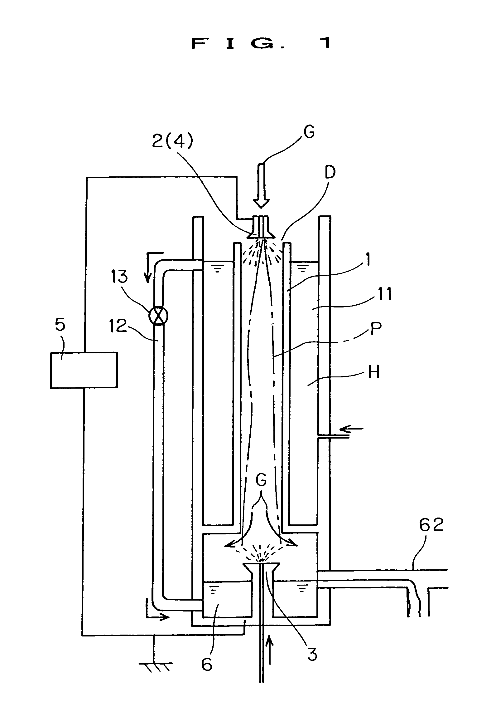
[0035]FIG. 1 shows the first embodiment of the exhaust gas treating system according to the present invention.

[0036]This exhaust gas treating system is intended for decomposing and treating harmful matters contained in the exhaust gas such as PFC gas as represented by CF4, SF6, etc., for example, by means of plasma generated between electrodes under the atmospheric pressure.

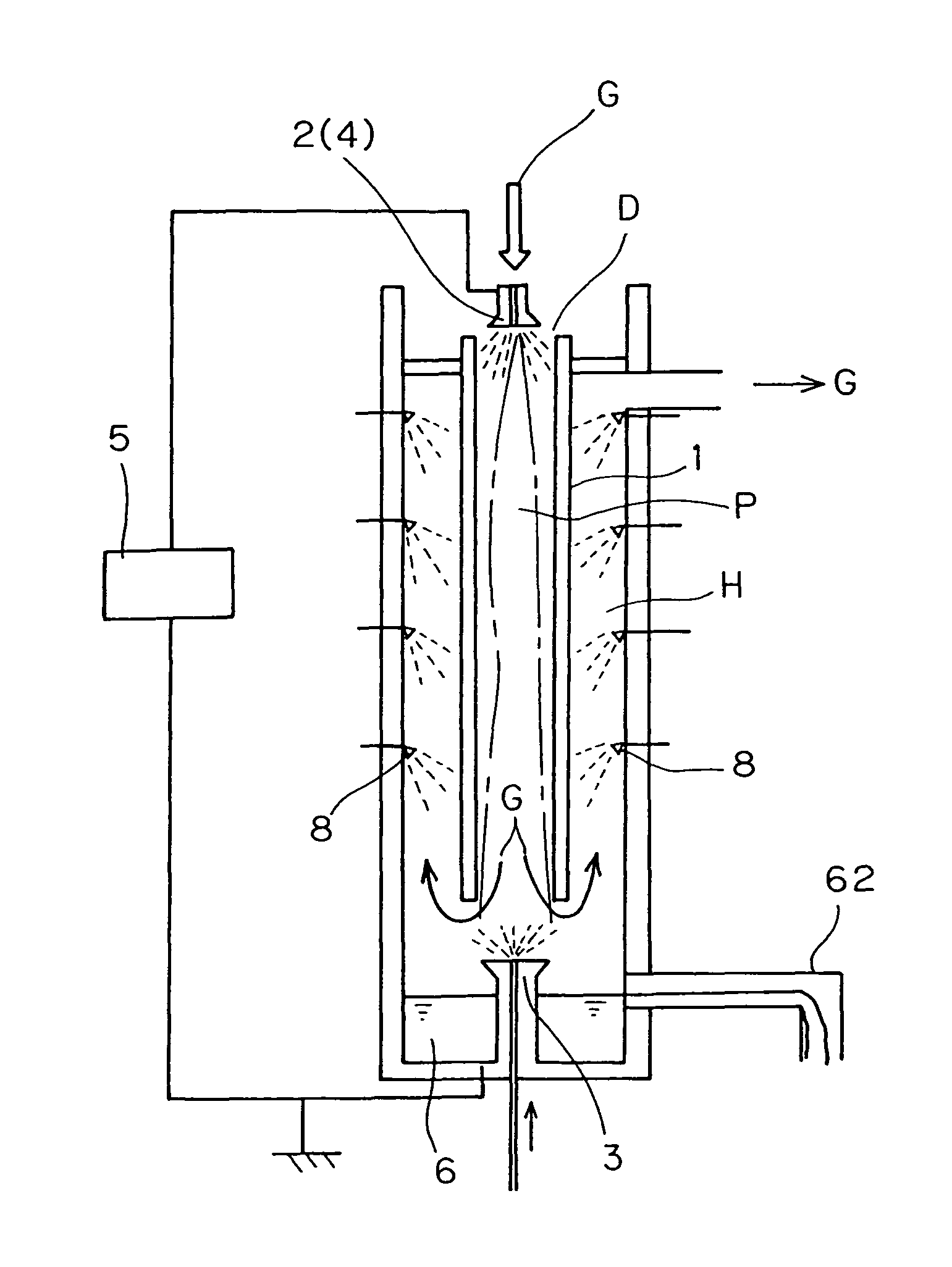
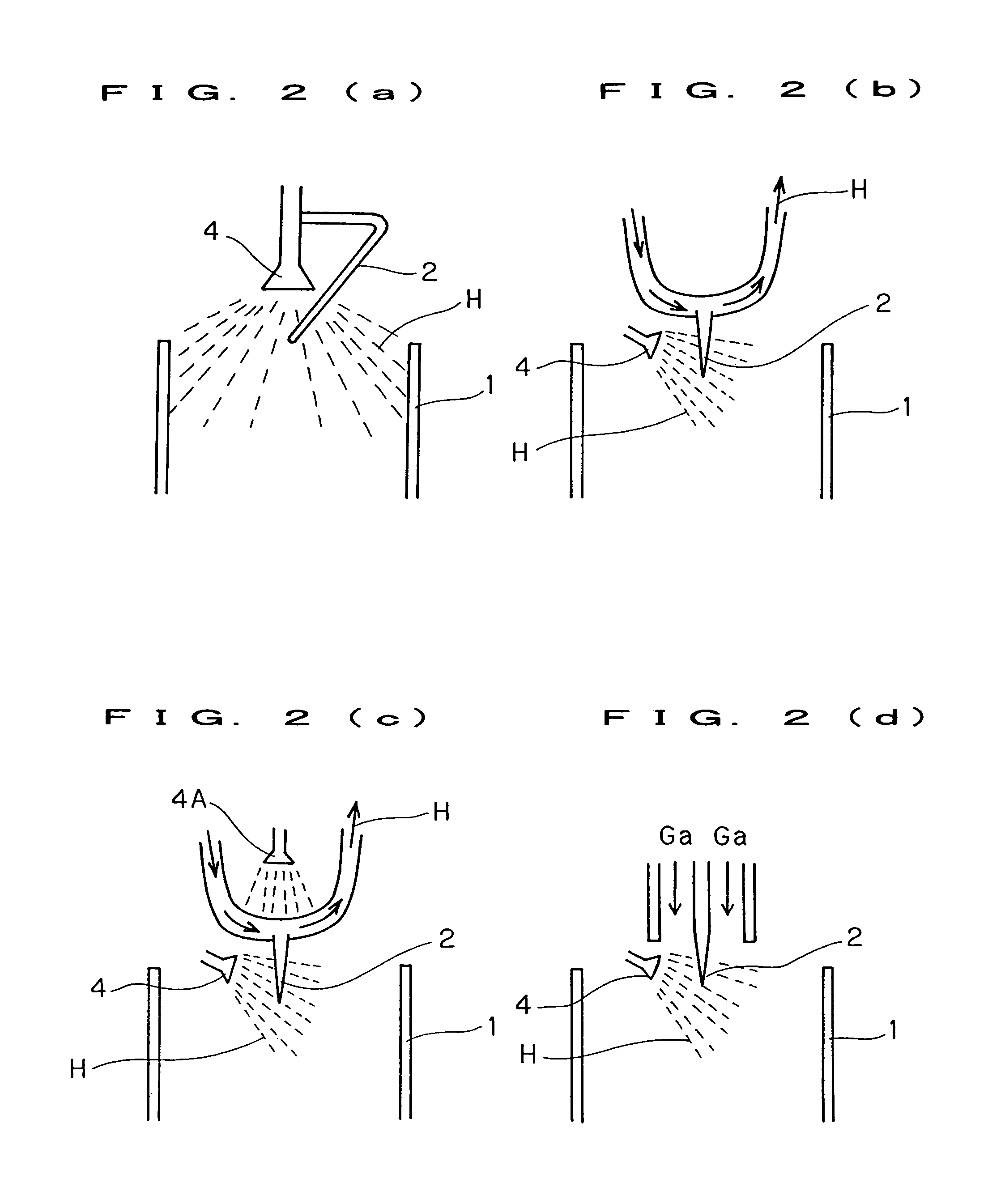
[0037]And, this exhaust gas treating system comprises a reaction tube 1 for introducing exhaust gas G, an upper electrode 2 disposed in the air on the top side of the reaction tube 1, a lower electrode 3 disposed on the bottom side of the reaction tube 1, and a spray nozzle 4 for spraying an electrolytic solution D between the upper electrode 2 and the lower electrode 3 (in this embodiment, the upper electrode 2 is designed to also serve as spray nozzle 4 for spraying an electrolytic solution), so as to form a path of electric current between the electrodes 2, 3 and generate plasma P in the reaction tube 1, by sp...

embodiment 2

[0063]FIG. 4 shows the second embodiment of the exhaust gas treating system according to the present invention.

[0064]This exhaust gas treating system comprises a reaction tube 1 for introducing exhaust gas G, an upper electrode 2 disposed in the air on the top side of the reaction tube 1, a lower electrode 3 disposed on the bottom side of the reaction tube 1, and a spray nozzle 4 for spraying an electrolytic solution D between the upper electrode 2 and the lower electrode 3, so as to form a path of electric current between the electrodes 2, 3 and generate plasma P in the reaction tube 1.

[0065]The reaction tube 1, realized in the form of a vertically installed cylinder, is composed of alumina, mullite, quartz, ceramics such as zirconia, etc. and other heat-resistant materials.

[0066]Although the reaction tube 1 may also be of air-cooled type, around the reaction tube is provided, in this embodiment, a water-cooling jacket 11 for cooling the reaction tube 1 at the time of generation of...

embodiment 3

[0080]FIG. 5 shows the third embodiment of the exhaust gas treating system according to the present invention.

[0081]This exhaust gas treating system, having the lower electrode 3 formed in a bottomed cylindrical shape, is designed to support this lower electrode 3 with a feed-water pipe 7.

[0082]The water H in the water tank 6 is discharged from an overflow line 65 provided at the center of the tank.

[0083]Other constructions of this third embodiment are the same as those of the respective embodiments described above and, therefore, one same signs and numerals will be given to one same members, and the explanation thereof will be omitted.


PUM

PropertyMeasurementUnit
corrosionaaaaaaaaaa
timeaaaaaaaaaa
tensionaaaaaaaaaa

Abstract

The present invention, aiming at providing an exhaust gas treating system capable of increasing the exhaust gas treating volume, through increase of the diameter of the reaction tube, stabilizing the state of generation of plasma without requiring any water membrane, and improving the harmful matters removing performance by extending the plasma length, comprises a reaction tube 1 for introducing exhaust gas G, an upper electrode 2 disposed in the air on the top side of the reaction tube 1, a lower electrode 3 disposed on the bottom side of the reaction tube 1, and a spray nozzle 4 for spraying an electrolytic solution D between the upper electrode 2 and the lower electrode 3, so as to form a path of electric current between the electrodes 2, 3 and generate plasma P in the reaction tube 1, by spraying an electrolytic solution D between the upper electrode 2 and the lower electrode 3.

Description

BACKGROUND OF THE INVENTION[0001]The present invention concerns a treating system of exhaust gas such as PFC gas, etc., more specifically an exhaust gas treating system for decomposing and treating harmful matters contained in the exhaust gas by means of plasma generated between electrodes.[0002]Conventionally, proposal is made of exhaust gas treating systems for decomposing and treating harmful matters contained in the exhaust gas means of plasma generated between electrodes (for example, Japanese Laid-open Patent Publication No. H5-15737 (patent literature 1), Japanese Laid-open Patent Publication No. H7-47224 (patent literature 2), Japanese Laid-open Patent Publication No. H11-156156 (patent literature 3), and Japanese Laid-open Patent Publication No. 2004-209373 (patent literature 4)).[0003]Of those inventions, the exhaust gas treating system described in the patent literature 4 comprises a reaction tube in the shape of a slender pipe through which to pass the gas to be treated,...

Claims


Application Information

Patent Timeline
Patent Type & Authority Patents(United States)
IPC IPC(8): B01D53/70B01J19/08H05H1/24B01D53/32
CPCB01D2251/404B01D53/32B01D53/70Y10S422/906B01D2257/2066B01D2259/818B01D2251/304B01D2251/604H05H1/24B01D2257/204B01D2251/402B01D2251/206H05H1/48H05H2245/15
Inventor AWAJI, TOSHIONAKAYAMA, TAKASHI
Owner CLEAN TECH CO LTD
Learn More