
Ultra-low frequency noise external cavity semiconductor laser with integrated waveguide grating and modulation section electronically stabilized by dual frequency feedback control circuitry

Active Publication Date: 2014-11-11
OPTASENSE
View PDF8 Cites 24 Cited by
  • Summary
  • Abstract
  • Description
  • Claims
  • Application Information

AI Technical Summary

Benefits of technology

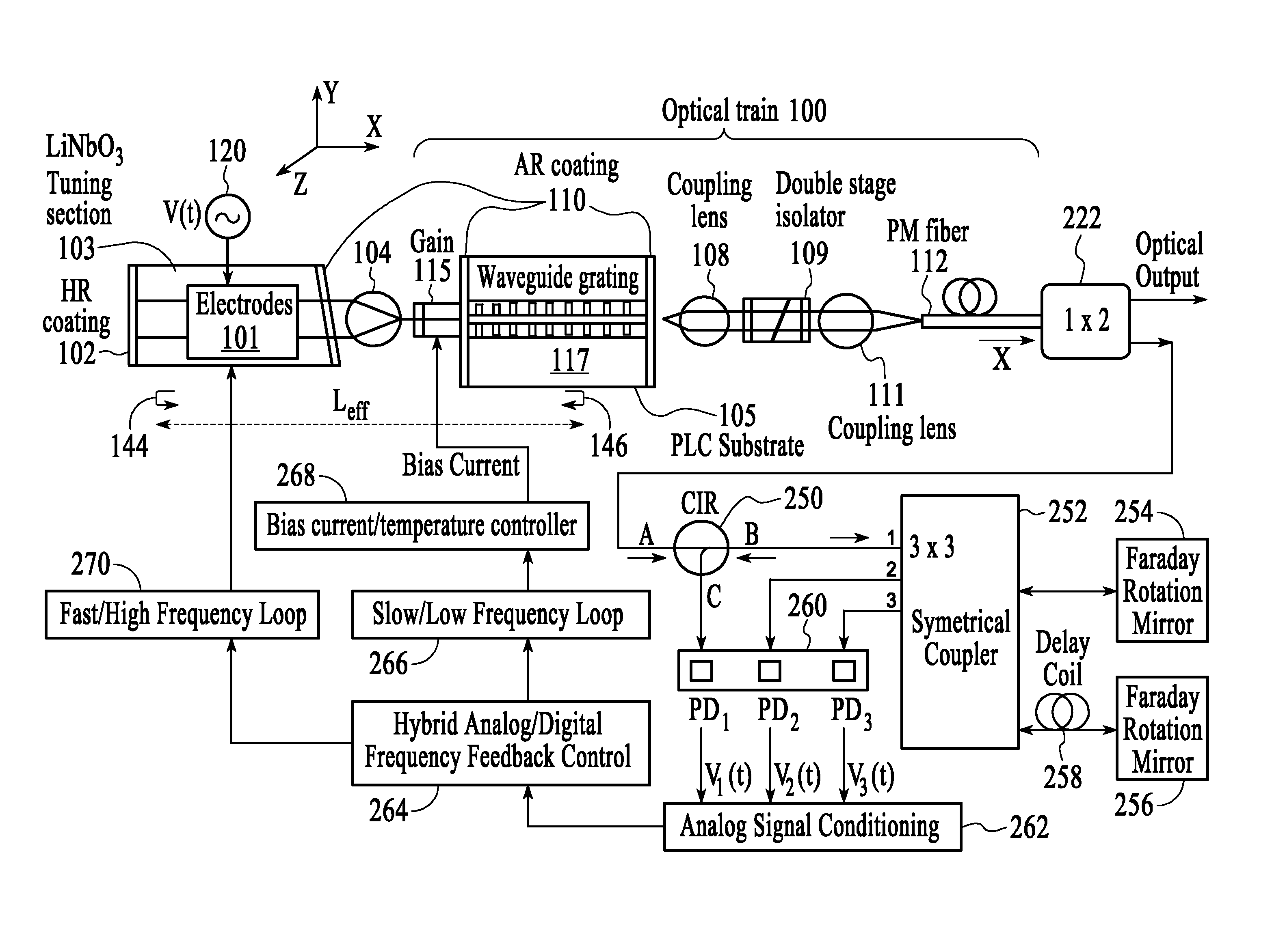
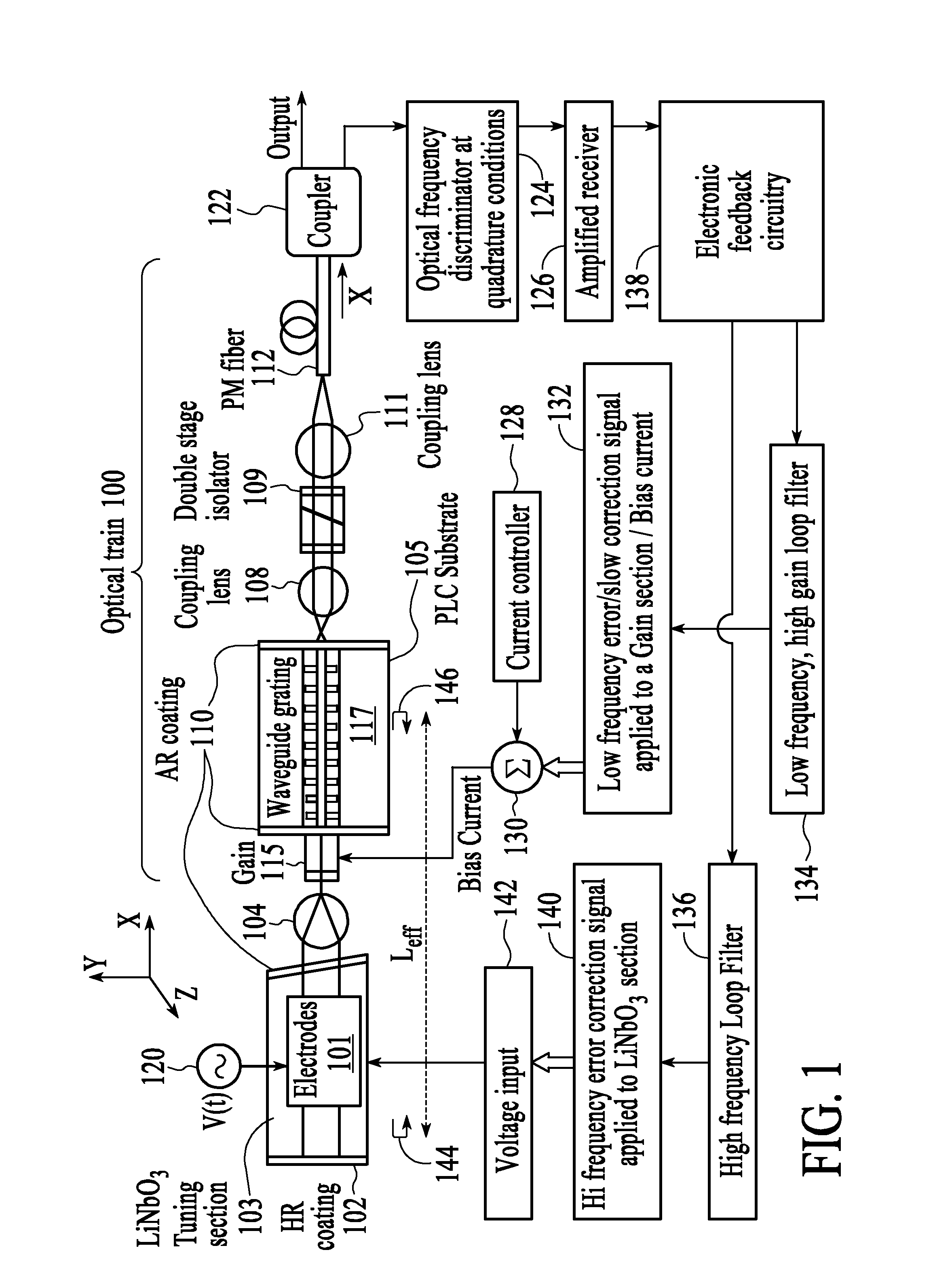
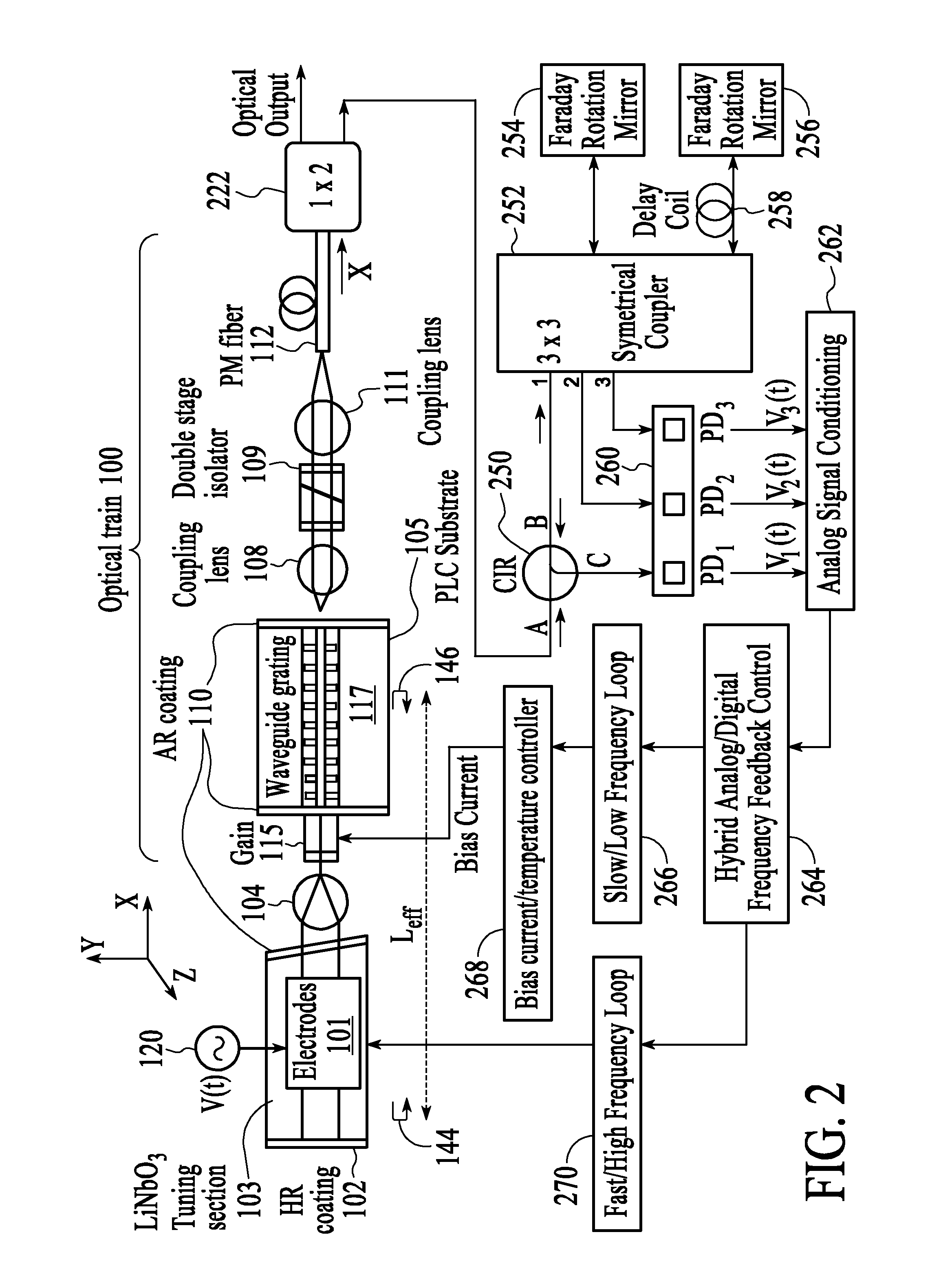
The present invention is a laser source that uses a special method to reduce noise. It uses an external cavity laser source with dual input terminals, including a bias current and a voltage signal. The laser source is stabilized by a dual electronic feedback circuitry applied to both the gain section and the modulation section. Additionally, the invention includes an optical frequency discriminator for more accurate measurements. These technical effects improve the performance and accuracy of optical devices that use the laser source.

Problems solved by technology

Secondly, optical discriminators that convert laser frequency noise δv to voltage, noise δV, must have large sensitivity (δV / δv) for such conversion.

Method used


Image

  • Ultra-low frequency noise external cavity semiconductor laser with integrated waveguide grating and modulation section electronically stabilized by dual frequency feedback control circuitry
  • Ultra-low frequency noise external cavity semiconductor laser with integrated waveguide grating and modulation section electronically stabilized by dual frequency feedback control circuitry
  • Ultra-low frequency noise external cavity semiconductor laser with integrated waveguide grating and modulation section electronically stabilized by dual frequency feedback control circuitry

Examples


Embodiment Construction

[0019]The present invention will now be described in detail with reference to the drawings, which are provided as illustrative examples of the invention so as to enable those skilled in the art to practice the invention. Notably, the figures and examples below are not meant to limit the scope of the present invention to a single embodiment, but other embodiments are possible by way of interchange of some or all of the described or illustrated elements. Moreover, where certain elements of the present invention can be partially or fully implemented using known components, only those portions of such known components that are necessary for an understanding of the present invention will be described, and detailed descriptions of other portions of such known components will be omitted so as not to obscure the invention. Embodiments described as being implemented in software should not be limited thereto, but can include embodiments implemented in hardware, or combinations of software and...


PUM


Abstract

Embodiments of the present invention use an external cavity laser source with dual input terminals, such as bias current for a gain section, and a voltage signal for a modulator section. An aspect of the present invention provides an ultra-low frequency noise external cavity frequency modulated (FM) semiconductor laser source frequency stabilized by a dual electronic feedback circuitry applied to semiconductor gain section and a modulation section. A further aspect of the present invention provides an optical frequency discriminator based on homodyne phase demodulation using an unbalanced Michelson interferometer with fiber optics delay and a symmetrical 3×3 optical coupler.

Description

CROSS REFERENCE TO RELATED APPLICATION[0001]This application claims priority from U.S. Provisional Application Ser. No. 61 / 651,409, filed May 24, 2012, the contents of which are incorporated herein by reference.FIELD OF THE INVENTION[0002]The present invention relates generally to stable operation of external cavity lasers (ECL), and particularly to dual frequency feedback control circuitry for semiconductor lasers with external cavity.BACKGROUND[0003]It is known that in the most demanding applications for fiber optic interferometric sensors, such as geophones, hydrophones and distributed Coherent Rayleigh (CR) effect based sensors require ultra-low frequency noise laser sources. Ultra-low frequency noise laser sources are also required in other applications, such as, precision navigation and atomic clocks. Industrial applications such as continuous wave (CW) coherent Doppler LIDAR and remote Laser Doppler Vibrometry (LDV) require ultra-low excess noise contribution, i.e. very narro...

Claims


Application Information

Patent Timeline
Patent Type & Authority Patents(United States)
IPC IPC(8): H01S5/068H01S3/10
CPCH01S5/06817H01S5/0687H01S5/141H01S5/02284H01S5/0064H01S3/107H01S5/0617H01S5/005H01S5/02251
Inventor KUPERSHMIDT, VLADIMIR
Owner OPTASENSE
Learn More