Control unit and medical examination apparatus

a control unit and medical examination technology, applied in the field of control units and medical examination equipment, can solve the problems of inconvenient condition, increased flow rate, and narrowing that cannot be compensated for by the elasticity of the vessel,

Inactive Publication Date: 2014-11-11
SIEMENS HEALTHCARE GMBH
View PDF5 Cites 0 Cited by
  • Summary
  • Abstract
  • Description
  • Claims
  • Application Information

AI Technical Summary

Benefits of technology

[0006]Starting from this premise, an object is to disclose a control unit and a medical examination apparatus with the aid of which an injection device and an imaging modality for an examination can be better coordinated with one another.
[0014]In an advantageous development, an alarm event leads to the equipment arrangement being switched to a safety mode. In this case, depending on the particular embodiment variant, the transition to the safety mode is initiated by the monitoring device itself or by the control unit, which in this case either is actuated by the monitoring device or accesses the monitoring device's information by way of a signal communication connection. Since by preference the equipment arrangement is switched to a safety mode fully automatically, a time delay, due for example to an operator's reaction time, can be avoided, as a result of which critical situations for the patient can be ruled out to the maximum possible extent.
[0015]Beneficial in this regard is an embodiment of the control unit in which the injection rate of the injection device is reduced in the safety mode. As a result the patient's stress state is usually also reduced to a lower level if an alarm event occurs, thereby avoiding a possible critical situation for the patient. Even if in this case the initially proposed value for the control variable is not reached, there is still the possibility that the stress level reached at this point in time is sufficient for the actual examination to such an extent that the already running examination does not have to be aborted without a data acquisition.
[0018]It is furthermore of advantage if the injection rate is increased during the data acquisition, starting from a predefined base value, at a predefined rate of increase until the proposed stress state is reached. In this way the injection rate which brings about the proposed stress state in the individual patient is approached incrementally with each examination.
[0020]According to another very beneficial embodiment variant, the measurement device and / or the monitoring device are / is embodied for measuring a heart rate, the heart rate being provided as a control variable and / or as a check variable. The heart rate is suitable for example during the cardiac perfusion examination both as a control variable which represents the stress state of the heart, and as a check variable which accurately reflects the general condition of the patient. For this specific examination it is accordingly possible to realize a particularly simple equipment arrangement in which the measurement device and the monitoring device are embodied by means of a common device. It is, however, preferred that the measurement device and the monitoring device are realized by means of redundantly operating measurement devices which are preferably controlled by a common control unit. In addition, a further alternative embodiment is provided in which the measurement device and the monitoring device are in each case realized by means of an independent device including a dedicated control unit, and in which the control units are connected to one another for signal communication purposes, in which case the control unit of the monitoring device takes precedence over the control unit of the measurement device if an alarm event occurs.

Problems solved by technology

Only under stress does the blood flow rate increase to such an extent that that the narrowing possibly can no longer be compensated for by the elasticity of the vessel.
Moreover, some patients are in a condition which is not conducive to their being exposed to a physical stress.
The examination of the patient by means of the imaging modality, in other words the MRT system, is accordingly carried out independently of how the patient actually responds to the injection, so that the desired specification of the stress state for the purpose of investigating the cardiac perfusion is only possible to a limited extent in this case.

Method used


Image

  • Control unit and medical examination apparatus
  • Control unit and medical examination apparatus

Examples


Embodiment Construction

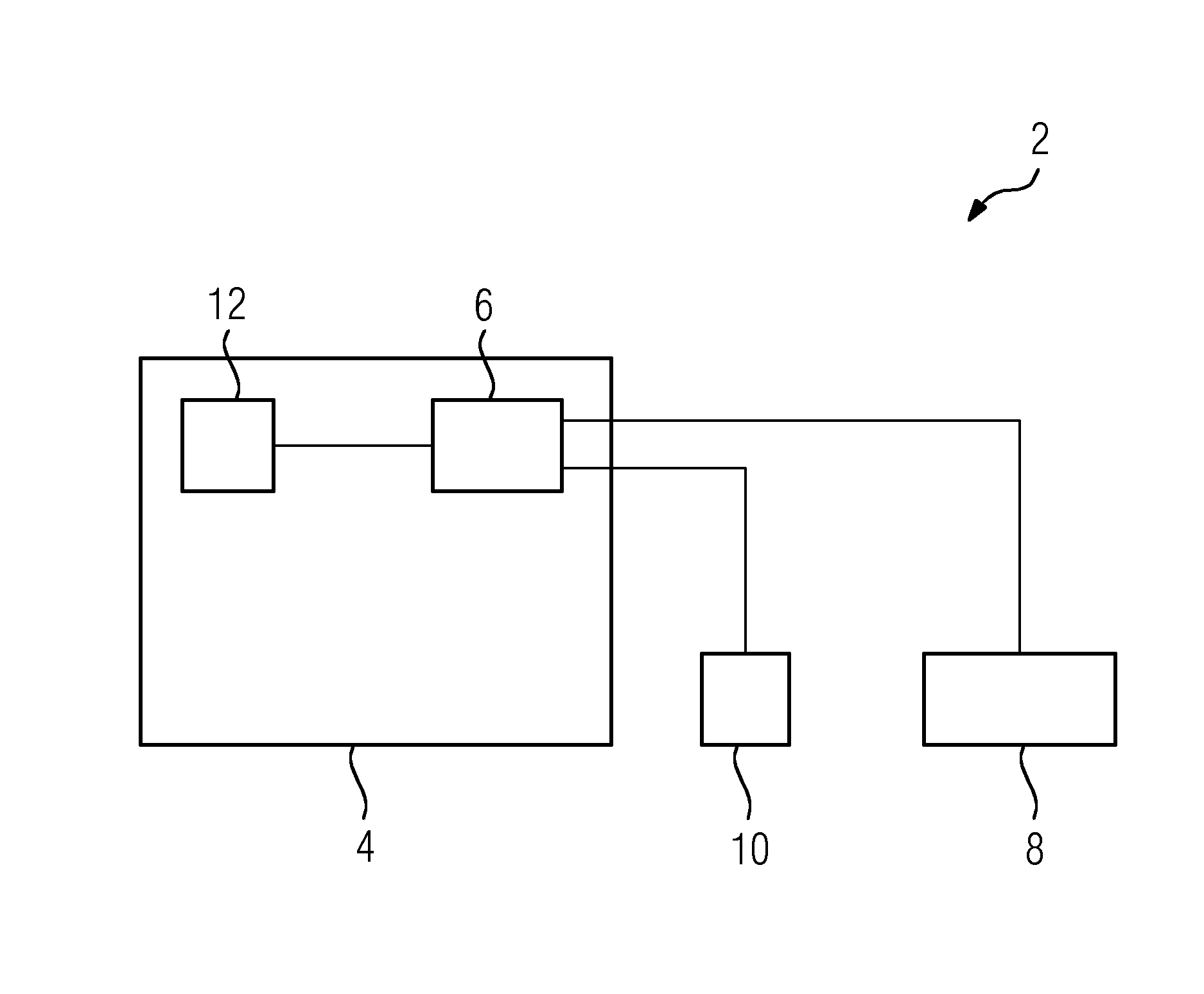
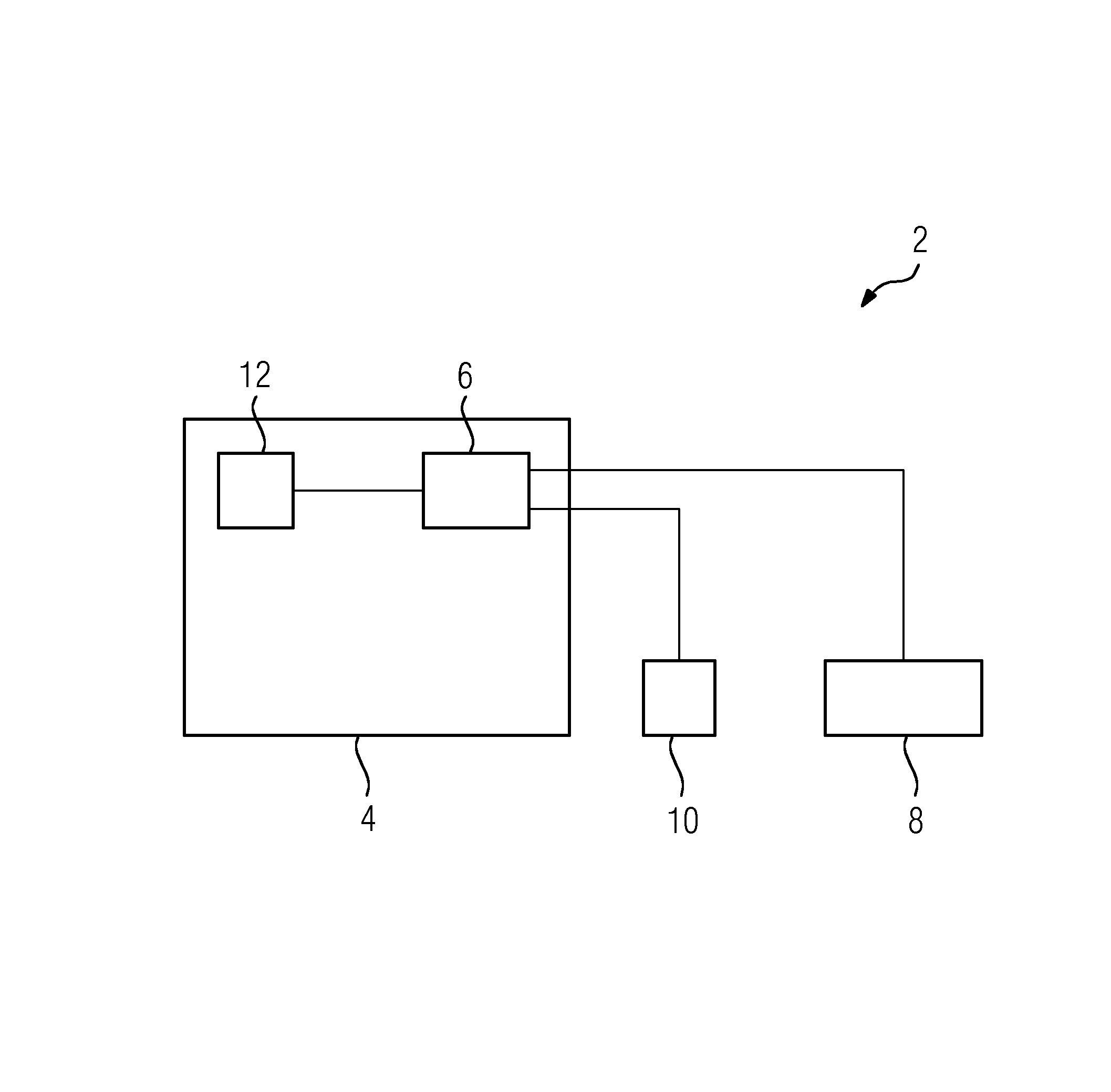
[0034]In the case of the medical examination apparatus 2 described hereinbelow and represented schematically in FIGURE, a magnetic resonance tomography system 4, MRT 4 for short, having a central control unit 6 is used for examining a patient by means of an imaging method. Depending on the chosen examination method, it is additionally provided to inject a regulatory substance into the patient. For this purpose the medical examination apparatus 2 includes an injection device 8, embodied in this instance by way of example as a syringe pump, also known as a dosing pump.

[0035]The injection device 8 used in the exemplary embodiment is a controllable injection device 8 which is connected to the control unit 6 of the MRT 4 for signal communication purposes and which is actuated by way of the control unit 6. In this way the injection of the regulatory substance and in particular the variation with time of the injection rate of the regulatory substance are adjusted to the chosen examination ...


PUM


Abstract

A control unit for an equipment arrangement is provided. The control unit includes an imaging modality, a measurement device for measuring a control variable and a controllable injection device for a regulatory substance influencing the control variable, wherein the injection rate of the injection device may be varied during a data acquisition such that a proposed value for the control variable is reached.

Description

CROSS REFERENCE TO RELATED APPLICATIONS[0001]This application claims priority of German application No. 10 2011 085 503.3 DE filed Oct. 31, 2011. All of the applications are incorporated by reference herein in their entirety.FIELD OF INVENTION[0002]A control unit and a medical examination apparatus is provided.BACKGROUND OF INVENTION[0003]When, for example, the cardiac perfusion, i.e. the circulation of blood through the heart, in a patient is to be examined by means of a magnetic resonance tomography (MRT) system, the cardiac perfusion is typically measured in a rest state on the one hand and in a stress state on the other. This is necessary because it can only be ascertained when coronary vessels are dilated under stress whether a stenosis, in other words a narrowing of the vessels, is functionally relevant. In the rest state the stenosis is usually “masked” by the compensatory dilation of the vessel. This means that a blood flow typical of the rest state is ensured owing to the e...

Claims


Application Information

Patent Timeline
Patent Type & Authority Patents(United States)
IPC IPC(8): A61B19/00A61M31/00A61B5/055A61B5/02A61B6/03A61B6/00
CPCA61B6/481A61B5/02A61B6/032A61B6/541A61B5/055A61B6/03A61B6/507A61B19/00A61B6/00A61B90/00
Inventor ASSMANN, STEFANHEISMANN, BJORNMERGES, RETOSCHMIDT, MARKUSSCHMIDT, SEBASTIANWESTPHAL, KERA
Owner SIEMENS HEALTHCARE GMBH
Why Eureka
Try Eureka