
Power tool

a power tool and tool body technology, applied in the field of power tools, can solve the problems of unintentional stirring resistance of accumulated lubricant, power transmission, various problems of traction drive, etc., and achieve the effect of reducing the scraping resistance of a lubricant, reducing the current load of the motor, and reducing the concavity and convexity

Inactive Publication Date: 2014-11-18
MAKITA CORP
View PDF20 Cites 0 Cited by
  • Summary
  • Abstract
  • Description
  • Claims
  • Application Information

AI Technical Summary

Benefits of technology

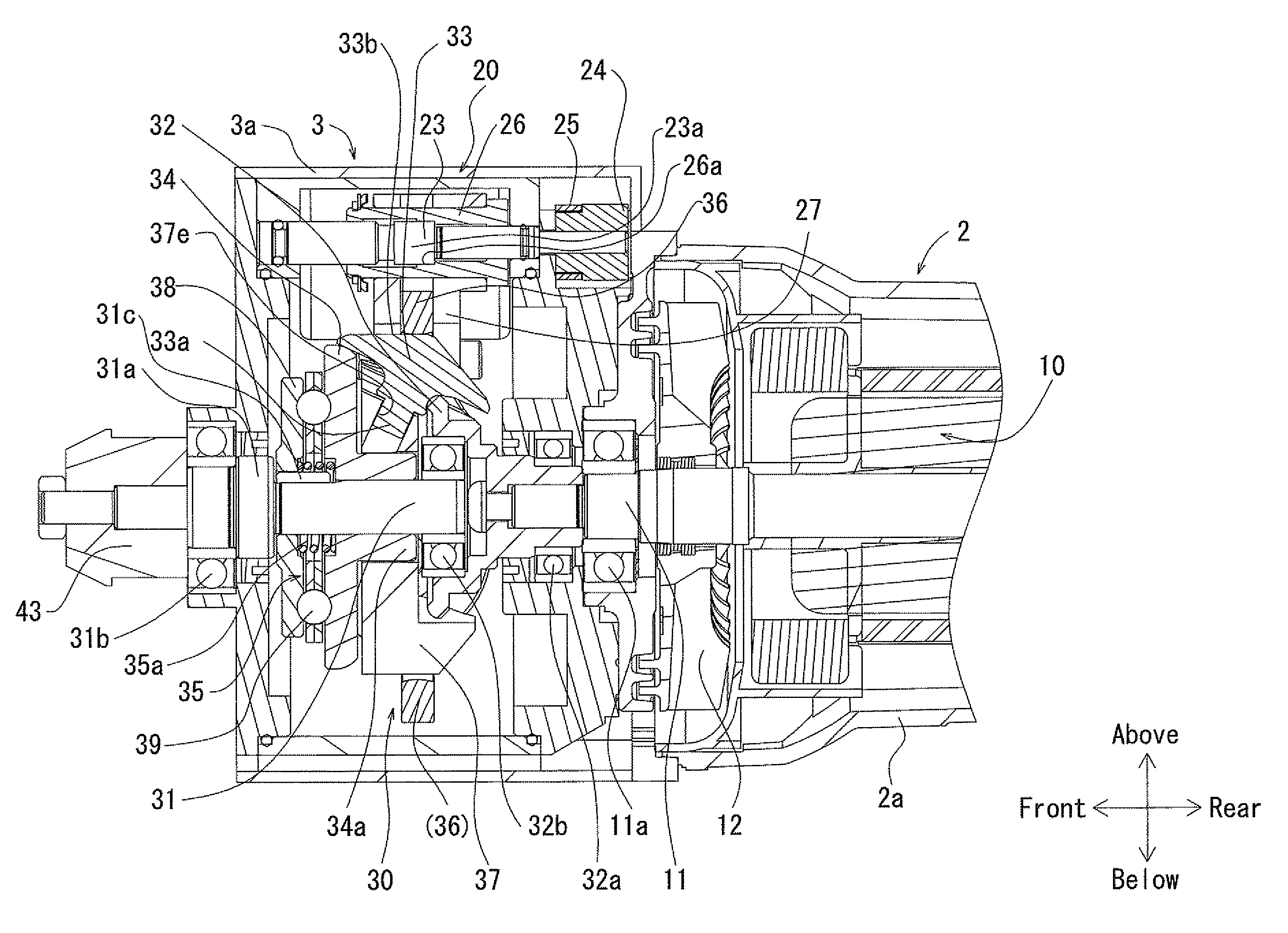
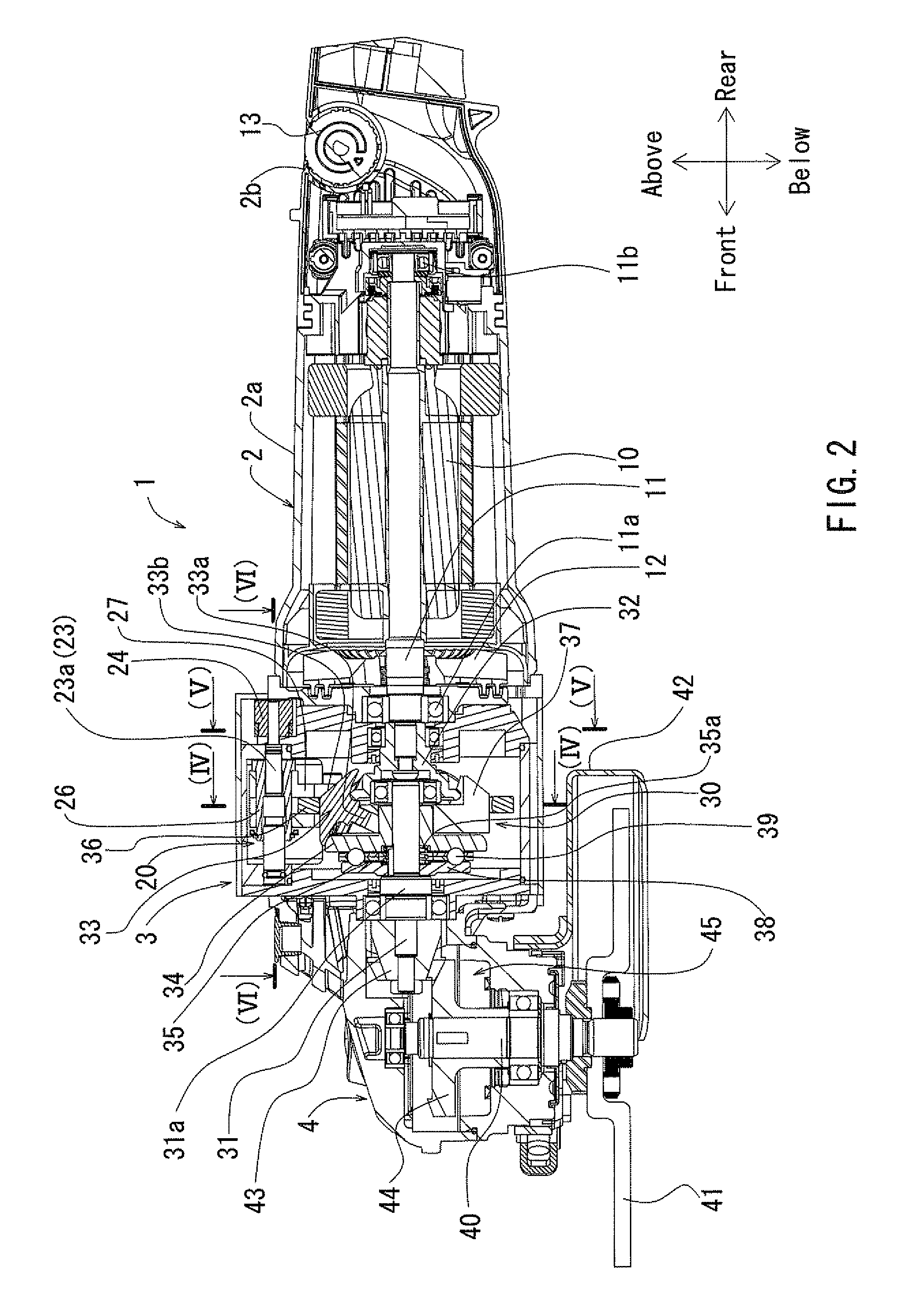
[0012]Preferably, the space between two planetary rollers adjacently located in the circumferential direction of the holder is filled with the resistance reducing portion. Consequently, it is possible to achieve an assembly closer to a smooth cylindrical shape by reducing concavities and convexities in the holder. As a result, it is possible to reduce scraping resistance of a lubricant, such as traction oil, when the planetary rollers revolve, which in turn, reduce the current load of the motor.

Problems solved by technology

A continuously variable transmission mechanism traction drive has various problems.
This operation results in power transmission.
Accumulated lubricant unintentionally becomes stirring resistance in the power transmission system.

Method used


Image

  • Power tool
  • Power tool
  • Power tool

Examples


Embodiment Construction

[0036]Each of the additional features and teachings disclosed above and below may be utilized separately or in conjunction with other features and teachings to provide improved power tools. Representative examples of the present invention, which utilize many of these additional features and teachings both separately and in conjunction with one another, will now be described in detail with reference to the attached drawings. This detailed description is merely intended to teach a person of ordinary skill in the art further details for practicing preferred aspects of the present teachings and is not intended to limit the scope of the invention. Only the claims define the scope of the claimed invention. Therefore, combinations of features and steps disclosed in the following detailed description may not be necessary to practice the invention in the broadest sense, and are instead taught merely to particularly describe representative examples of the invention. Moreover, various features...


PUM


Abstract

Embodiments of the present invention may include a power tool including a drive motor and a continuously variable transmission mechanism. The continuously variable transmission mechanism may include a sun roller rotated by a drive motor, the sun roller configured to press on a plurality of planetary rollers, a holder radially supporting the plurality of planetary rollers, a shift ring being in internal contact with the plurality of planetary rollers, and a resistance reducing portion disposed at the holder to fill a gap between the two of the planetary rollers.

Description

[0001]This application claims priority to Japanese patent applications serial number 2011-78036 and 2011-99778, the contents of which are incorporated herein by reference.BACKGROUND OF THE INVENTION[0002]1. Field of the Invention[0003]The present invention relates to a power tool, such as a disc grinder, an electric screwdriver, or a drill for boring, which is equipped with an electric motor therein as a power source.[0004]2. Description of the Related Art[0005]Such a power tool is generally equipped with either a gear train for changing the number of output revolutions of a motor or a gear train for changing the output direction. A CVT (Continuously Variable Transmission) that continuously varies the gear train and reduction ratio is commonly used as a transmission mechanism for power tools. Technology concerning CVT traction drives are disclosed, for example, in JP No. 6-190740 A, JP No. 2002-59370 A, and JP No. 3-73411 B2.[0006]In a continuously variable transmission traction dri...

Claims


Application Information

Patent Timeline
Patent Type & Authority Patents(United States)
IPC IPC(8): F16H57/08F16H15/52F16H57/04
CPCB24B47/12B25F5/001B24B23/028F16H15/52Y10T74/19642Y10T74/19665
Inventor MATSUNO, TADASUKEKOBAYASHI, KENJI
Owner MAKITA CORP
Learn More