Projection lens arrangement

a projection lens and arrangement technology, applied in the field of projection systems, can solve the problems of limited physical dimensions and limited control of adverse effects caused by aberration at the point of convergence, and achieve the effects of reducing spot size, reducing aberration, and increasing resolution

Active Publication Date: 2014-11-18
ASML NETHERLANDS BV
View PDF29 Cites 6 Cited by
  • Summary
  • Abstract
  • Description
  • Claims
  • Application Information

AI Technical Summary

Benefits of technology

[0014]The present invention aims to provide a multiple beamlet charged particle lithography system able to achieve smaller critical dimensions, for example 22 nm, while maintaining sufficient wafer throughput, for example between 10 and 60 wafers per hour. The insight underlying the present invention is that this higher resolution can be obtained in a multi-beamlet charged particle system by considerably reducing the spot size while at the same time considerably increasing the current generated in the system.
[0015]Not only is a reduced spot size required to achieve the desired performance, but also a reduced point spread function of beamlets is required to maintain sufficient exposure latitude. Sufficient exposure latitude requires a relatively high ratio of peak exposure level on the target from a beamlet compared to base or background level of exposure as normally caused by the peripheral Gaussian parts of neighbouring beamlets. Designing a system to generate beamlets having a smaller point spread function, however, considerably reduces the charged particle current that may be applied to the target by each beamlet.
[0017]The present invention solves this problem by providing array manipulators in the system, which may take various forms such as a group deflector array, a condenser lens array, or aperture array, for directing a plurality of beamlets in groups towards a single projection lens. This measure permits a considerable increase in the number of beamlets in the system, without a need to design and manufacture a lens miniaturized to the extreme extent as performed in the array manipulators. The invention thus teaches to avoid even further miniaturization in an area within the projection column where due to the size, pitch, vertical proximity and level of electric field strength, the risk of electric flash and consequent destruction of the lens system in operation already pose a significant problem. In contrast, miniaturization in the area of a beamlet manipulator, due to the absence of field strengths of a magnitude as encountered at the projection lens system, does not pose such operational effects, nor problems with manufacture that can not be overcome, e.g. as a consequence to the use of more or less standard MEMS manufacturing techniques of these components. Another insight underlying the present invention is that projection of a beamlet originating from a direction of convergence is effectively the same as deflection of a vertical beamlet. This implies that the measure according to the present invention does not induce or require a principle redesign of the existing final projection lens system known from the prior art. A third insight underlying the present invention is that converging only groups of beamlets avoids the presence of a common cross-over of all the beamlets in the entire system, i.e. of all of the charged particle current therein. Thus, the adverse effects caused by aberration at the point of convergence will be of a limited controlled effect. A fourth insight underlying the invention is that the ability to blank beamlets within the group of beamlets passing through a single projection lens results in “patterned beamlets” being projected onto the target.

Problems solved by technology

This creates a problem due to the limited physical dimensions of the projection optics in a multi-beamlet system, which are typically limited to a size corresponding to the size of the die to be exposed.
Thus, the adverse effects caused by aberration at the point of convergence will be of a limited controlled effect.

Method used


Image

  • Projection lens arrangement
  • Projection lens arrangement
  • Projection lens arrangement

Examples


Embodiment Construction

[0058]The following is a description of various embodiments of the invention, given by way of example only and with reference to the drawings.

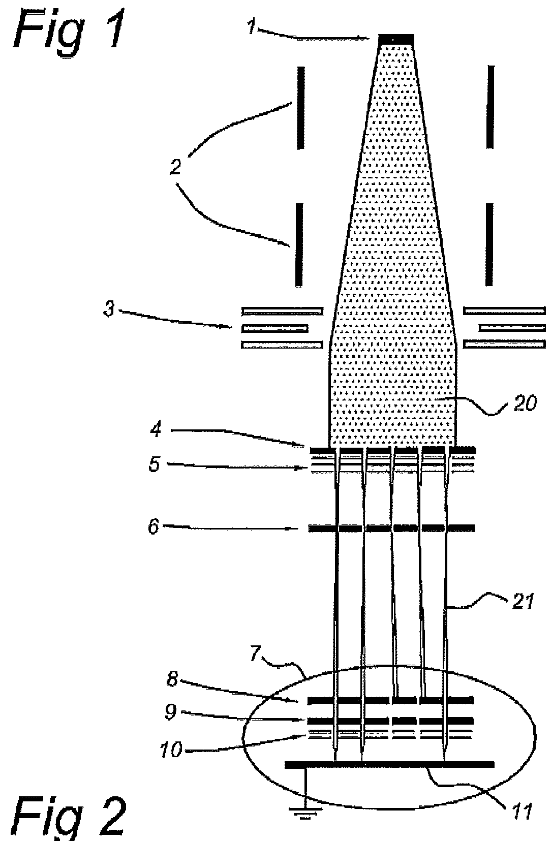
[0059]FIG. 1 shows a simplified schematic drawing of an embodiment of a charged particle multi-beamlet lithography system based upon an electron beam optical system without a common cross-over of all the electron beamlets. Such lithography systems are described for example in U.S. Pat. Nos. 6,897,458 and 6,958,804 and 7,084,414 and 7,129,502 which are all hereby incorporated by reference in their entirety, assigned to the owner of the present invention. In the embodiment shown in FIG. 1, the lithography system comprises an electron source 1 for producing a homogeneous, expanding electron beam 20. Beam energy is preferably maintained relatively low in the range of about 1 to 10 keV. To achieve this, the acceleration voltage is preferably low, the electron source preferably kept at between about −1 to −10 kV with respect to the target at ground ...


PUM


Abstract

A projection lens arrangement for a charged particle multi-beamlet system, the projection lens arrangement including one or more plates and one or more arrays of projection lenses. Each plate has an array of apertures formed in it, with projection lenses formed at the locations of the apertures. The arrays of projection lenses form an array of projection lens systems, each projection lens system comprising one or more of the projection lenses formed at corresponding points of the one or more arrays of projection lenses.

Description

CROSS REFERENCE TO RELATED APPLICATIONS[0001]This application is a continuation-in-part of U.S. application Ser. No. 12 / 393,050 filed on Feb. 26, 2009 which claims priority from U.S. provisional application No. 61 / 031,573 filed on Feb. 26, 2008, and is a continuation-in-part of U.S. application Ser. No. 13 / 397,814 filed on Feb. 16, 2012, which is a continuation of U.S. application Ser. No. 12 / 905,126 filed on Oct. 15, 2010, which is a continuation of PCT application number PCT / EP2009 / 054467 filed on Apr. 15, 2009 which claims priority from U.S. provisional application No. 61 / 045,243 filed on Apr. 15, 2008. The contents of all of these applications are hereby incorporated by reference in their entirety.BACKGROUND OF THE INVENTION[0002]1. Field of the Invention[0003]The present invention relates to a projection system for a charged particle multi-beamlet system, such as for a charged particle multi beamlet lithography system or an inspection system, and an end module for such a projec...

Claims


Application Information

Patent Timeline
Patent Type & Authority Patents(United States)
IPC IPC(8): B82Y10/00H01J37/30H01J37/317B82Y40/00H01J37/12
CPCH01J2237/121H01J37/3175B82Y40/00H01J37/12H01J37/3177H01J2237/1205H01J2237/0435H01J37/3007B82Y10/00H01J2237/151H01J2237/31774
Inventor WIELAND, MARCO JAN JACOKAMPHERBEEK, BERT JANVAN VEEN, ALEXANDER HENDRIK VINCENTKRUIT, PIETERSTEENBRINK, STIJN WILLEM HERMAN KAREL
Owner ASML NETHERLANDS BV
Why Eureka
Try Eureka