Method of providing through-thickness reinforcement of a laminated material

a laminated composite material and through-thickness technology, applied in the field of providing through-thickness reinforcement of laminated composite materials, can solve the problems of poor inter-laminar or through-thickness, mechanical properties in comparison to the corresponding in-plane properties, and limit the use of such materials for certain applications, so as to reduce the tendency of fibres

Active Publication Date: 2014-11-25
ROLLS ROYCE PLC
View PDF14 Cites 9 Cited by
  • Summary
  • Abstract
  • Description
  • Claims
  • Application Information

AI Technical Summary

Benefits of technology

[0038]By forming a plurality of holes in a single operation, the process can be significantly speeded up and the costs reduced. This makes the method more cost effective and thus commercially viable.

Problems solved by technology

A known problem with laminated composite materials is their poor inter-laminar, or through-thickness, mechanical properties in comparison to the corresponding in-plane properties.
Such low inter-laminar strength and fracture toughness can constrain the design of composite parts and may even limit the use of such materials for certain applications.
Such matrix materials are generally significantly more expensive than conventional matrix materials, often have poor high temperature properties and may still not provide a sufficient increase in fracture toughness.
When penetrating a fibre laminate with a needle of this size, significant cutting and deformation of the laminate's fibres can be caused.
This may result in reductions in the in-plane material properties in excess of 20%.
In addition, the use of a continuous fibre for the through-thickness reinforcement may cause a kink to form in the top few plies of the laminate as a result of the loop of fibre traversing from one stitch to the next.
This can also result in a reduction in the in-plane properties of the material.
A problem with conventional z-pinning techniques is that of the reinforcing fibres being deflected from the desired insertion trajectory by the interaction of the end chamfer with the densely packed fibres of the laminate.
This can result in the inserted fibres being incorrectly angled or curved relative to the plane of the laminate, which can significantly reduce their through-thickness reinforcing properties.
A further problem with the conventional z-pinning process is that the fibrous reinforcing pins can split or fracture during insertion as a result of the need to force the pins through the densely compacted fibre layers of the laminate.
This can reduce the effectiveness of the presence of the reinforcing pins.

Method used


Image

  • Method of providing through-thickness reinforcement of a laminated material
  • Method of providing through-thickness reinforcement of a laminated material
  • Method of providing through-thickness reinforcement of a laminated material

Examples


Embodiment Construction

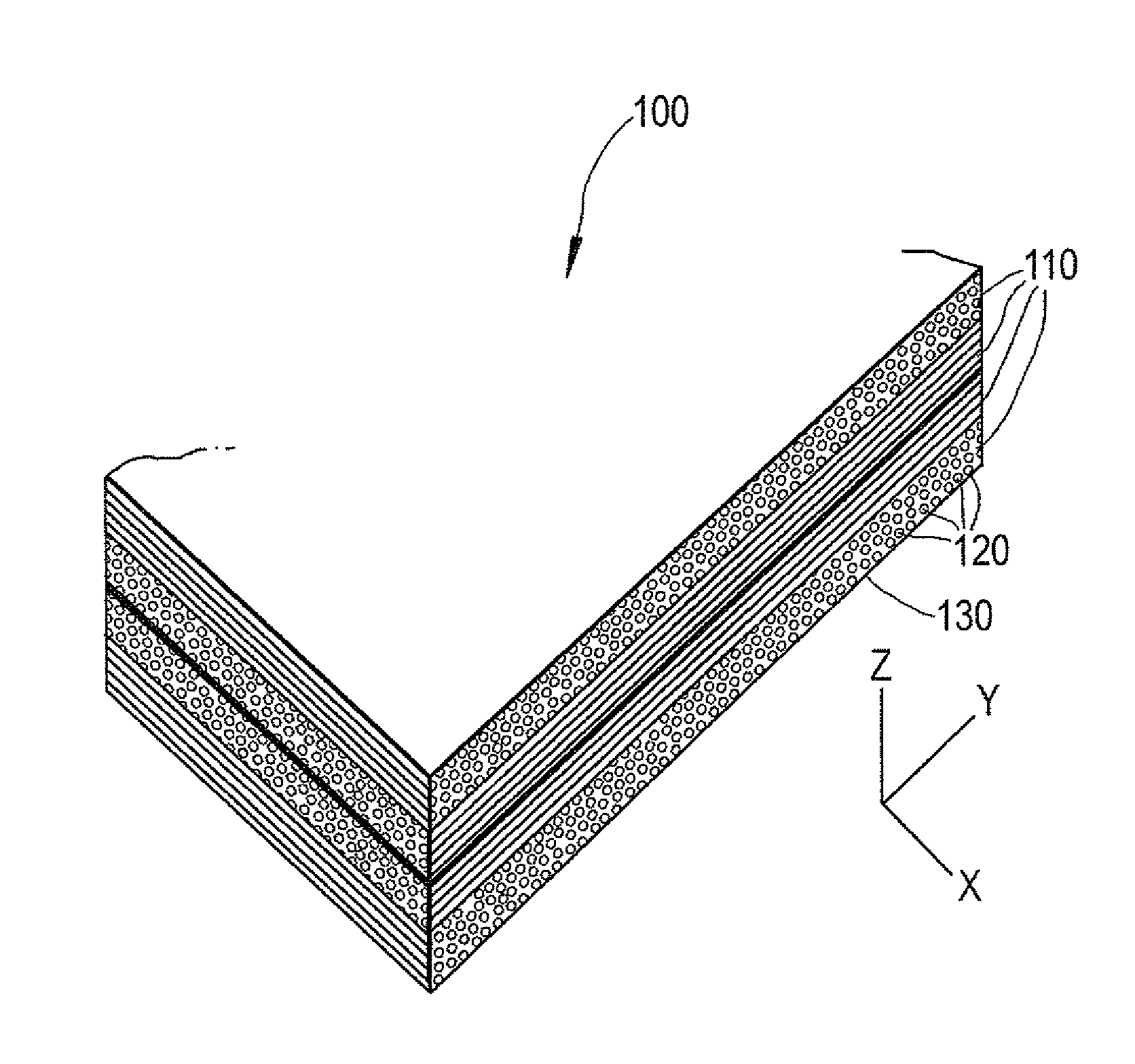
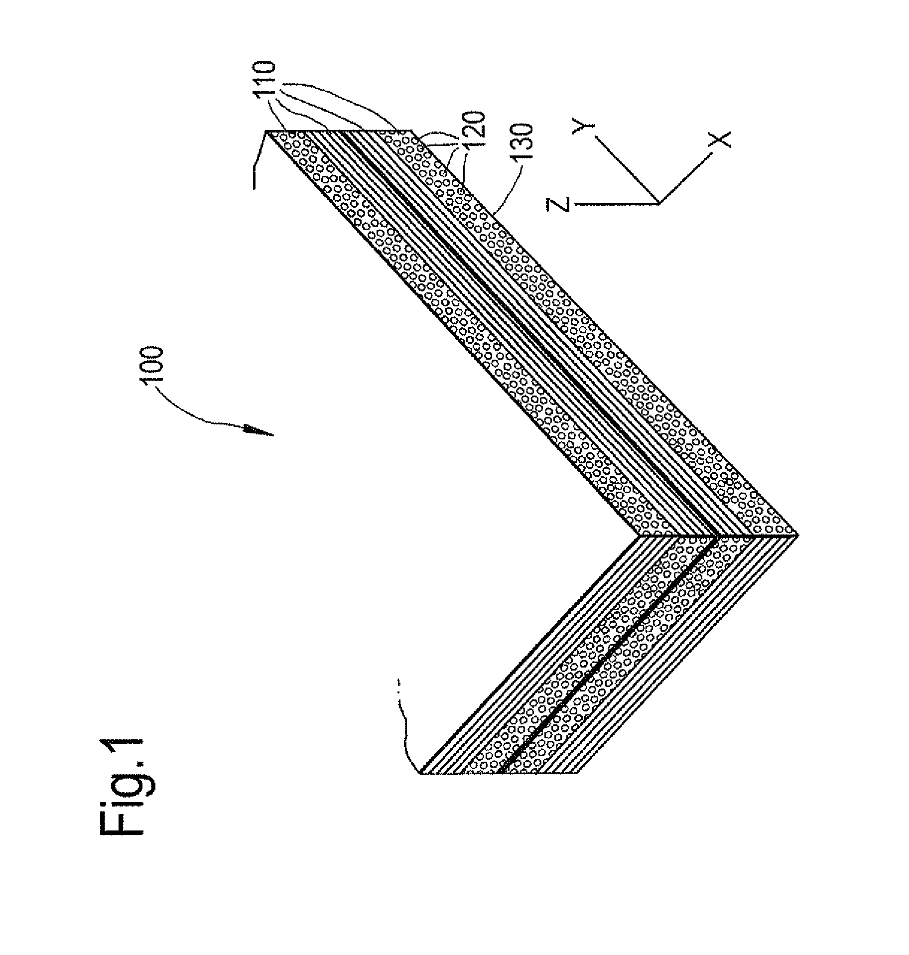
[0061]FIG. 1 shows an example of a laminated composite material 100 comprising a plurality of fibre layers 110. In the embodiment of FIG. 1, each of the fibre layers 110 comprises a plurality of uni-directionally aligned fibres 120 held within a matrix material 130. In alternative arrangements, the fibre layers may comprise fibres having other orientations.

[0062]The relative fibre orientation of each of the layers 110 together with the quantity of fibre layers 110 is determined by the design loads to which the finished component is to be subjected.

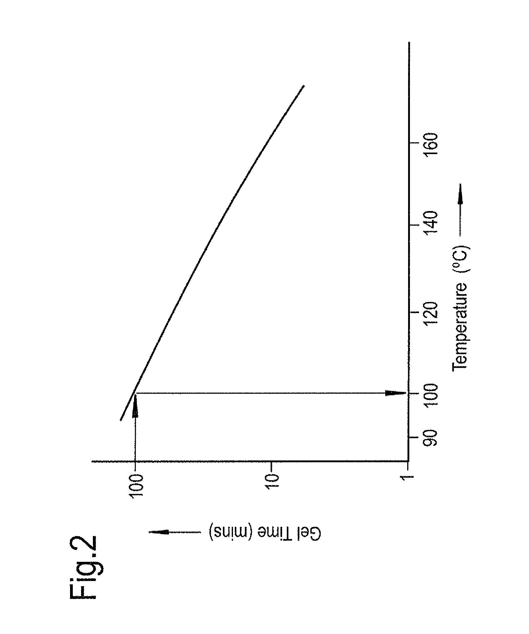
[0063]The method of the present invention involves heating the uncured composite laminate material 100 to a first pre-determined temperature.

[0064]The first pre-determined temperature will be unique to each matrix material 130 and is determined on the basis of the matrix material's curing parameters, rheology and gelation time, and the first pre-determined time interval.

[0065]The first pre-determined time interval is the time available to ...


PUM

PropertyMeasurementUnit
diameteraaaaaaaaaa
diameteraaaaaaaaaa
diameteraaaaaaaaaa

Abstract

A laminated composite material comprising a polymeric matrix material and plurality of fiber layers is heated to a first pre-determined temperature which is defined as the temperature at which there is a first pre-determined time interval until the matrix material reaches its gel point. The first pre-determined time interval being defined as the time required to insert the required quantity of through-thickness reinforcement fibers into the laminated material. A plurality of holes is formed in the laminated material; each hole being formed by inserting a needle having a conical tip, into the laminated material. A reinforcing element is then inserted into each of a respective one of the plurality of holes.

Description

[0001]This invention claims the benefit of UK Patent Application No. 1117467.9, filed on 11 Oct. 2011, which is hereby incorporated herein in its entirety.FIELD OF THE INVENTION[0002]This invention relates to a method of providing through-thickness reinforcement of a composite material and particularly, but not exclusively, to a method of providing through-thickness reinforcement of a laminated composite material.BACKGROUND[0003]Laminated composite materials, in which reinforcing fibres are held within a polymeric matrix, are extensively used in many engineering applications. Such materials can generally provide a higher strength and stiffness per unit weight than conventional metallic materials. This makes such composite materials advantageous for weight sensitive applications, such as those in the field of aerospace.[0004]A known problem with laminated composite materials is their poor inter-laminar, or through-thickness, mechanical properties in comparison to the corresponding in...

Claims


Application Information

Patent Timeline
Patent Type & Authority Patents(United States)
IPC IPC(8): B29C70/24B23P19/04
CPCB29C70/24Y10T29/49826Y10T156/1056Y10T428/24273
Inventor LANDER, JAMES, KEITH
Owner ROLLS ROYCE PLC
Why Eureka
Try Eureka