Controlled motion system

a technology of motion system and control, which is applied in the direction of motor/generator/converter stopper, multiple dynamo-motor starters, dynamo-electric converter control, etc., can solve the problems of difficult to know the position of a mover, and difficult to speed up or slow down movers

Active Publication Date: 2014-11-25
ROCKWELL AUTOMATION
View PDF6 Cites 32 Cited by
  • Summary
  • Abstract
  • Description
  • Claims
  • Application Information

AI Technical Summary

Benefits of technology

[0009]In another preferred embodiment soft magnetic composite materials are used for the motor core of the controlled motion system. This advantageously allows nonlinear shaped smart sections with complex core geometries to be utilized without the large core losses of prior art systems. Also, soft magnetic composite cores allow the windings to be directly wound onto the core pole pieces and then assembled into the motor core, reducing assembly costs.
[0011]In a preferred embodiment of the invention the controlled motion system includes a control system which is coupled at more than one motor for driving the movers along more than one simple sections of the track and for increasing or decreasing the speed of the movers as they travel along the simple section(s).
[0020]In another preferred embodiment of the invention the controlled motion system includes a control system connected to the Internet for facilitating remote control of the controlled motion system.

Problems solved by technology

One problem with prior art systems is that it is often difficult to know the position of a mover as it travels along both the smart sections and the simple sections.
Further, it is often difficult to speed up or slow down movers as they travel along the entire track as well as changing the pitch (or distance) between movers as they move along the simple sections.

Method used


Image

  • Controlled motion system
  • Controlled motion system
  • Controlled motion system

Examples


Embodiment Construction

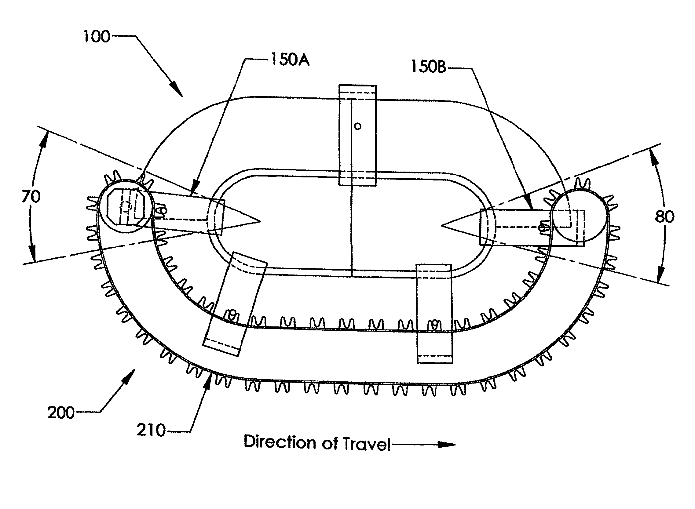
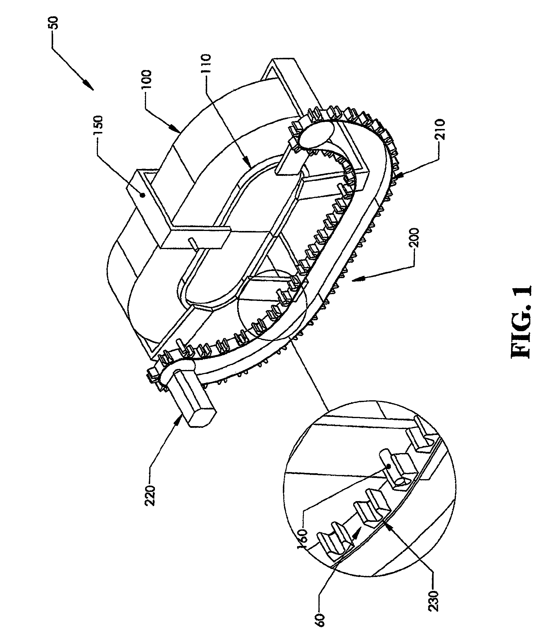
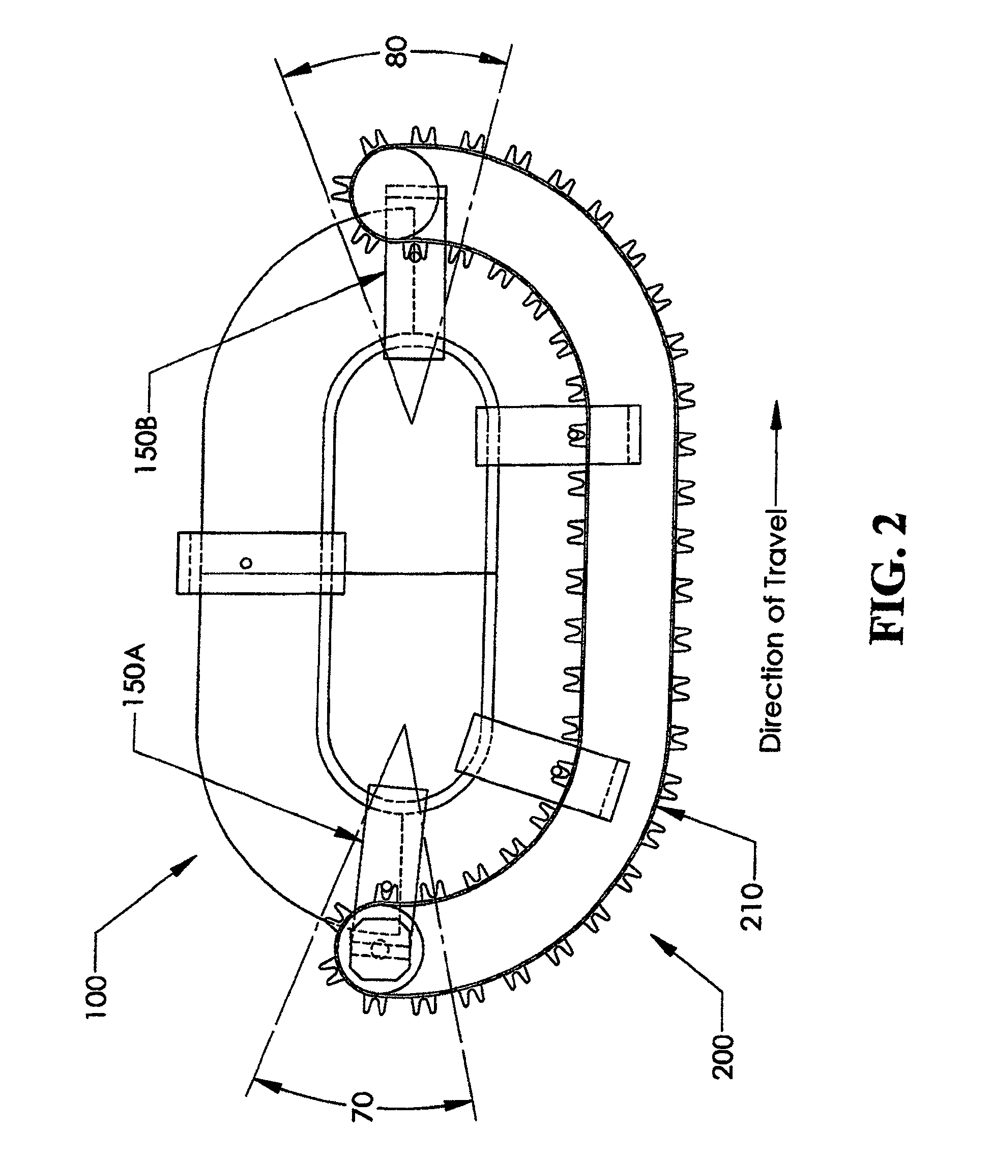
[0033]FIG. 1 illustrates a preferred embodiment a controlled motion system 10 having of a hybrid track 50, comprised of at least one “smart” section 100 and at least one “simple” section 200. Movers 150 are movably mounted on bearing system 110 such that the movers are constrained to transverse a path defined by this bearing system 110. A “smart” section 100 is characterized by its ability to independently control each of the movers 150 that is in its realm of control. This type of motor section is known and disclosed in U.S. Pat. No. 6,876,107. In contrast, a “simple” section 200 typically lacks the ability to independently control each of the movers 150 but instead moves all of the movers traveling along that simple section 200 together.

[0034]In a preferred embodiment as shown in FIG. 1, the simple section 200 comprises a belt or chain 210 driven by a wheeled, chained, linear or rotary motor 220. The belt or chain 210 has at least one driving feature 230 that couples to a driven f...


PUM


Abstract

A controlled motion system having a plurality of movers controlled as they travel along both smart and simple sections of a track. The controlled motion system comprises a control system for controlling the speed of a mover as it travels along a simple section, and permits the pitch or distance between movers to increase or decrease as they travel along a simple section. In a preferred embodiment the controlled motion system includes at least one coupling feature having a driving feature on a simple section for engaging and operably driving a driven feature on each mover such that positive control of each mover is maintained throughout its transition from a smart section to a simple section.

Description

CROSS REFERENCE TO RELATED APPLICATION[0001]The present invention claims benefit of U.S. provisional Patent Application No. 61 / 629,310, filed Nov. 16, 2011, the disclosure of which is hereby incorporated by reference in its entirety.BACKGROUND OF THE INVENTION[0002]The present invention relates to controlled motion systems and more particularly, to controlled motion systems capable of independently controlling multiple movers on a track.[0003]Systems incorporating linear motor sections that provide independent control of multiple moving elements have been used in a wide variety of processes (e.g. packaging, assembly automation, processes involving use of machine tools, etc.) and provide the advantage of increasing both the speed and flexibility of the process. Since linear motors employ a moving magnetic field to directly drive the moving element (hereinafter referred to as “movers”), they eliminate or reduce the gear heads, shafts, keys, sprockets, chains and belts often used with ...

Claims


Application Information

Patent Timeline
Patent Type & Authority Patents(United States)
IPC IPC(8): B65G43/00H02P31/00B65G54/02H02P25/06
CPCB65G54/02B65G43/00H02P31/00H02P25/06H02P5/50
Inventor WERNERSBACH, GLEN C.JACOBS, KEITH G.
Owner ROCKWELL AUTOMATION
Why Eureka
Try Eureka