Bracket for use in building construction

a technology for building construction and brackets, applied in the direction of building reinforcements, construction, building roofs, etc., can solve the problems of imposing a significant load on the structure of the building, weakening and crumbling of masonry veneer, and rigid aggregate structure, so as to reduce the likelihood, weather resistant, and damage the effect of masonry veneer

Active Publication Date: 2014-12-02
RODGERS RICHARD BRADLEY
View PDF18 Cites 5 Cited by
  • Summary
  • Abstract
  • Description
  • Claims
  • Application Information

AI Technical Summary

Benefits of technology

[0032]One feature of the present invention is that the bracket is insertable through a masonry veneer and is configured and sized so that the surface area of the bracket that contacts the masonry veneer is significantly larger and greater than the surface area of the connector member. This feature has the advantage of dispersing the forces that are exerted on the connector member by the first and second building members over a larger area on the masonry veneer, with this area generally being defined by the walls of the bracket member. This dispersion of forces has the advantage of significantly reducing the likelihood that the connector member will split, crumble or fissure the mortar or masonry member within the masonry veneer, and thereby damage the masonry veneer.
[0033]It is also a feature of the present invention that a connector support is preferably made from a metal member that is co-molded with an injection moldable plastic that forms this first and second bracket portions. This feature has the advantage of enabling the device to be both weather resistant, low cost, and strong.
[0034]The plastic of the bracket portions makes the device generally inexpensive to manufacture, while making the device resistant to rust and other degradations that may be more common to metal than plastic parts. The metal connector supports, by being made of metal, can be easily made to be strong enough to resist the pressures that are exerted by the connector member on the connector support. Additionally, the use of the metal support can help to make the brackets definitely more rigid and better capable of withstanding forces than the use of the plastic bracket alone.

Problems solved by technology

Although workable while wet, mortar becomes hard when it sits and thereby results in a rigid aggregate structure.
Unfortunately, there are certain occasions wherein a builder may wish to desire to place a point or line load upon a masonry veneer, of a type, that may cause the masonry veneer to weaken and crumble.
As an example, an outside wooden deck that may be coupled to the house and built exteriorly of the masonry veneer will itself impose a significant load on the structure of the building to which it is attached because of the weight of the wood and the amount of the wood necessary to create the deck.
Although the nature of the wood from which the rim board and ledger board and sheathing board are made tend to make these devices wooden boards well suited for withstanding the forces imposed by a cylindrical connector member such as a bolt, the brick or mortar through which the bolt passes is not so well suited to absorb these forces.
For that reason, it is often non-code compliant to use connector bolts that extend between the rim board and the ledger board and pass directly through the masonry veneer.
As discussed above, the difficulty with the use of such a connector bolt is that the small line load created by such a connector member can deleteriously effect the mortar or brick through which it passes.

Method used


Image

  • Bracket for use in building construction
  • Bracket for use in building construction
  • Bracket for use in building construction

Examples


Embodiment Construction

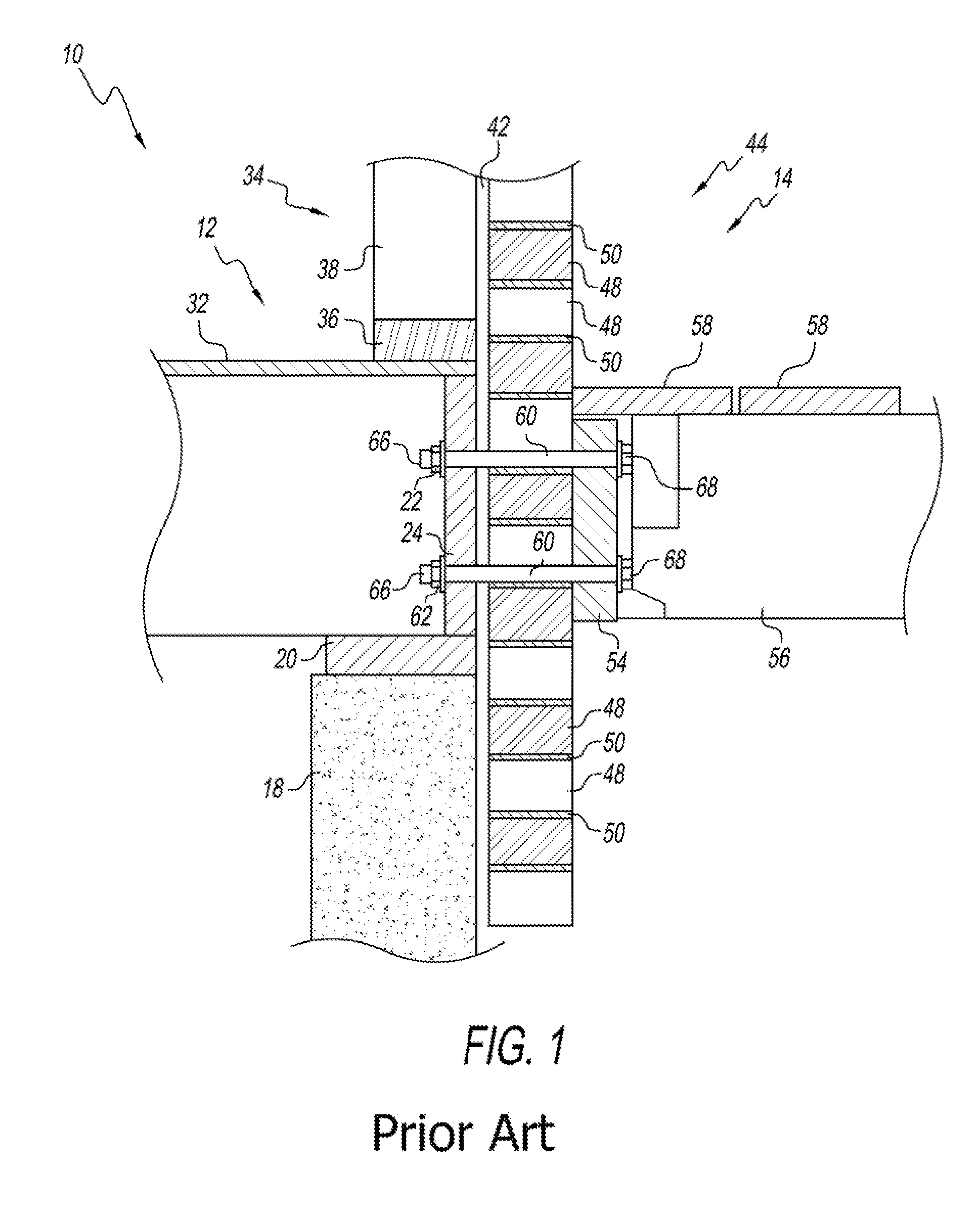
[0057]Before the present invention is described, it is helpful to review the prior art, so that one can help distinguish the invention from the prior art. To that end, the reader's attention is directed to FIG. 1, wherein a prior art wall and connector system 10 is shown. The prior art wall and connector system include an interior building member 12, that is comprised primarily of the house frame, and an exterior building member 14 that here is shown as a deck. Although the exterior building member 12 is shown as a deck, it will be appreciated that the invention is applicable with a variety of other exterior building members including, but not limited to porches, pergolas, balconies, signs, window boxes and stairs and other exteriorly disposed building components that exert force on the building through their weight and / or have force exerted on them by the weight of other items, such as people, furniture and the like. As will be described in more detail below, a connector apparatus ...


PUM


Abstract

A bracket for a building that includes a first building member, a masonry veneer disposed exteriorly of the first building member, and a second building member disposed exteriorly of the masonry veneer. The bracket includes a bracket body having a first portion for being coupled to the first building member and a second outwardly extending portion having a length sufficient to extend to at least about an exterior surface of the masonry veneer. A connector member extends through the bracket member, and at least partially through each of the first and second building members. A connector support extends through the bracket body and includes a sleeve having a passageway for receiving and supporting the connector member, wherein the bracket body and connector support are configured to distribute a load borne by the connector member on the masonry veneer over an area of the bracket body greater than the area of the connector.

Description

PRIORITY STATEMENT[0001]The present invention claims benefit of priority to Rodgers, U.S. provisional patent application No. 61 / 671,712, that was filed on 14 Jul. 2012 and is fully incorporated herein by reference.I. TECHNICAL FIELD OF THE INVENTION[0002]The present invention relates to building products, and more particularly to building products for use in connection with coupling building components such as decks, signs, porches and the like that are disposed exteriorly of a building to an interiorly disposed frame member of the building.II. BACKGROUND[0003]There are many ways to construct buildings. One technique that is very popular for use in residential structures and smaller commercial buildings is a construction technique wherein a wood or metal frame is placed upon a concrete or cinder block foundation. Often, the frame is overlain with both an interior covering layer such as drywall, and an exterior covering layer. A wide variety of exterior covering layer materials can b...

Claims


Application Information

Patent Timeline
Patent Type & Authority Patents(United States)
IPC IPC(8): E04B1/38E04B1/00
CPCE04B1/38E04B1/003
Inventor RODGERS, RICHARD BRADLEY
Owner RODGERS RICHARD BRADLEY
Why Eureka
Try Eureka