Shaft arrangement having a shaft which extends within a fluid-filled casing

a fluid-filled casing and shaft technology, applied in the field of mechanical engineering, can solve the problems of undesired low pressure in the region, difficult conditions for the transmission of pump power via the shaft, and general undesired effects, so as to avoid excessive resuction of fluid, avoid gas bubble production, and reduce the effect of resuscitation

Active Publication Date: 2014-12-02
ECP ENTWICKLUNGSGMBH
View PDF212 Cites 27 Cited by
  • Summary
  • Abstract
  • Description
  • Claims
  • Application Information

AI Technical Summary

Benefits of technology

[0010]For example, the sleeve can be connected securely to the shaft and can rotate correspondingly at the same speed of rotation as the latter. The sleeve can have, on the outside thereof, a helical blade structure or individual blades or webs in a corresponding inclined or helical construction. It is thereby important that the sleeve produces a flow or a pressure rise counter to the flow direction, i.e. in the direction of the shaft end or towards the connection chamber. As a result, a low pressure in the connection chamber and the inflow of air through a ventilation opening or the shaft leadthrough is effectively prevented. Also excessive resuctioning of the fluid is avoided, if this is delivered subsequently through a fluid inflow. By means of the sleeve, the pressure is increased towards the drive-side shaft end, whilst it is somewhat reduced on the side of the sleeve remote from the drive due to the suctioning. In this region, the conveying directions of the shaft, on the one hand, and of the sleeve, on the other hand, act against each other so that the pressure tends to drop there. In this region, there is however no inflow and no opening so that the production of gas bubbles there can be avoided.
[0011]Hence the invention has the effect that the shaft can be operated reliably at high speeds of rotation without cooling and / or lubrication by the fluid being interrupted and without gas bubbles being conveyed along the shaft towards the end of the catheter remote from the drive.
[0012]Also in the case of other uses in the non-medical field, such a bubble formation in a fluid surrounding the shaft is undesired and can be prevented with the means of the invention.

Problems solved by technology

For this purpose, not only do the corresponding pumps require to have a very small constructional size but also difficult conditions are present for the transmission of the pump power via a shaft.
This effect is generally undesired since it produces a pressure drop in the fluid in the catheter.
If however the pump of the fluid supply line does not provide an adequate volume flow, then a low pressure which is undesired is produced in the region of the fluid inflow as a result of the suction tendency of the shaft.

Method used


Image

  • Shaft arrangement having a shaft which extends within a fluid-filled casing
  • Shaft arrangement having a shaft which extends within a fluid-filled casing
  • Shaft arrangement having a shaft which extends within a fluid-filled casing

Examples


Embodiment Construction

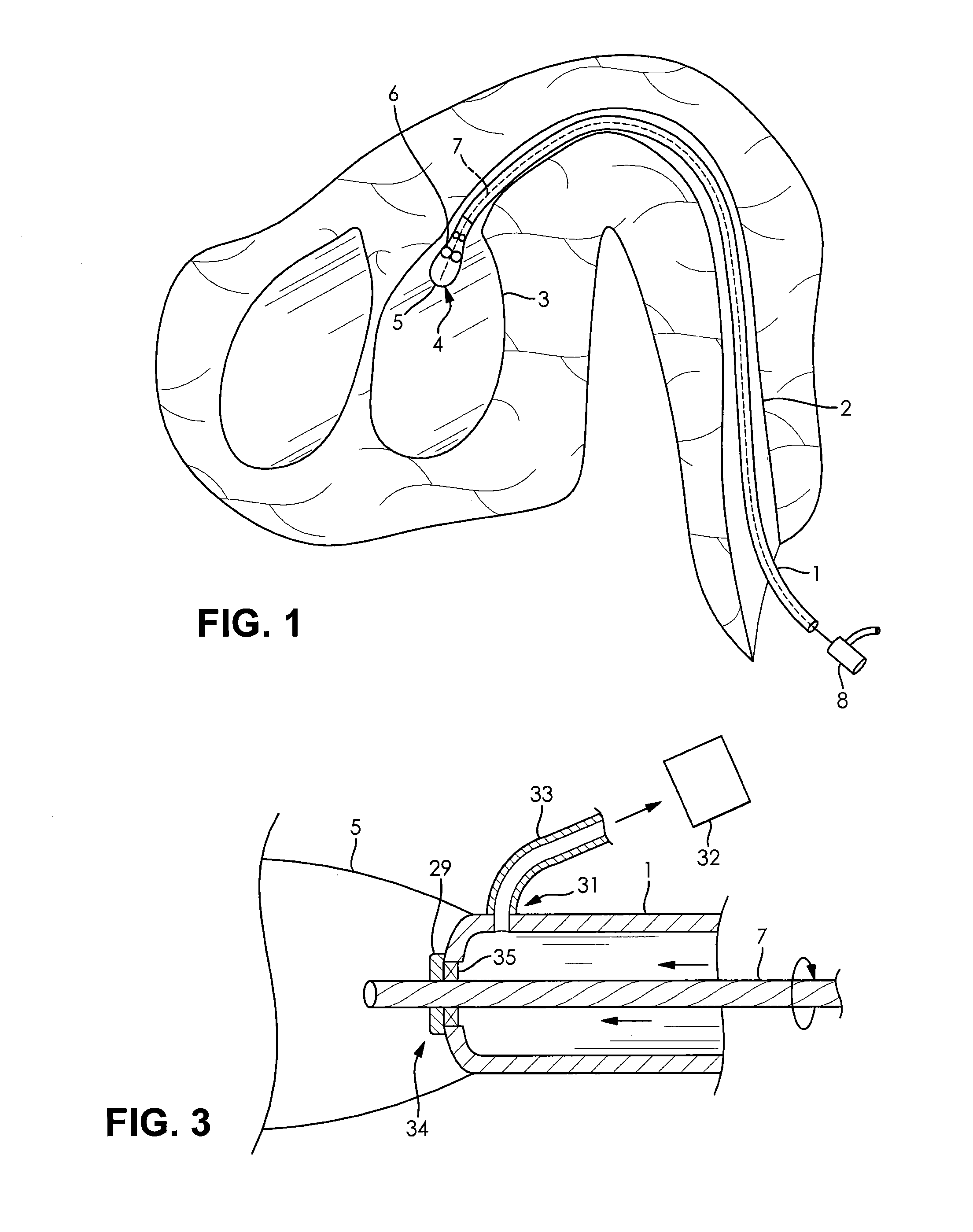
[0030]FIG. 1 shows a typical application of the shaft arrangement according to the invention in the medical field in conjunction with a heart pump. A catheter 1 is hereby provided, which is pushed through a blood vessel into a ventricle 3 and which has a micropump 4 at the distal end thereof. Said micropump has a housing 5 in which a rotor 6 can be actuated to rotate mechanically by means of a shaft 7.

[0031]The shaft 7 is guided through a leadthrough of the pump housing 5 into the catheter 1 in a sealed manner and is guided through the catheter 1 up to a shaft drive situated outwith the body in the form of a motor 8.

[0032]The pump housing 5 and the rotor 6 are normally configured in the case of such a heart catheter pump such that they can be compressed for introduction into the ventricle through the blood vessel and can be expanded within the ventricle. In order to remove the pump from the body, the latter is compressed again in order to be able to withdraw it through the vessel by...


PUM


Abstract

In the case of a shaft arrangement having a shaft (7) which extends within a casing (1) filled with a fluid and which can be actuated by means of a drive (8) from outwith the casing (1), the shaft (7) having on its outer peripheral surface a surface structure which conveys the fluid in a flow direction (30) in the longitudinal direction of the shaft during rotation, a sleeve (19) is provided according to the invention, which can rotate with the shaft and has at least one conveying element (20) for conveying the fluid in a counterflow direction opposite to the flow direction. As a result, a bubble-free conveyance of the fluid along the shaft (7) is facilitated.

Description

FIELD OF INVENTION[0001]The invention resides in the field of mechanics or mechanical engineering and can be used with particular advantage in precision mechanics, i.e. in the construction of small machines and appliances.BACKGROUND OF THE INVENTION[0002]Use in medical technology offers particular advantages, where frequently, in particular in the case of minimally invasive medical procedures, movements via shafts, in particular flexible shafts, must be transmitted through small openings or vessels occurring naturally in the body under particularly difficult surrounding conditions.[0003]A particular type of application is represented by the actuation of liquid pumps in microconstruction, which are applied for example as heart pumps and which can be brought with a heart catheter to the operating place thereof, for example a ventricle.[0004]For this purpose, not only do the corresponding pumps require to have a very small constructional size but also difficult conditions are present f...

Claims


Application Information

Patent Timeline
Patent Type & Authority Patents(United States)
IPC IPC(8): A61B17/00A61M1/10A61M1/12F16C1/24F16C1/06
CPCA61M1/101F16C1/06A61M1/12A61B2017/00685F16C1/24A61M1/125F16C2316/10A61M60/818A61M60/414A61M60/148A61M60/824A61M60/422A61M60/216A61M60/562A61M60/13
Inventor LIEBING, REINER
Owner ECP ENTWICKLUNGSGMBH
Why Eureka
Try Eureka