Methods and systems for interference mitigation

a technology of interference mitigation and interference prevention, applied in the field of wireless communication, can solve the problems of limiting the spectrum efficiency/throughput of cell edge users, limiting the coverage of control channels, and limiting the interference mitigation effect of these types of systems, and achieve the effect of enhancing interference mitigation

Active Publication Date: 2014-12-02
CENT OF EXCELLENCE & WIRELESS TECH
View PDF22 Cites 3 Cited by
  • Summary
  • Abstract
  • Description
  • Claims
  • Application Information

AI Technical Summary

Benefits of technology

[0010]Another embodiment herein provides a method of enhancing interference mitigation in a wireless telecommunication network, the method comprising repeating incoming modulation symbols over a first subcarrier and a second subcarrier; complex conjugating the repeated modulation symbols over the second subcarrier, wherein the complex conjugating is synchronized in multiple spatially separated transmitters; and transmitting the repeated symbols over the first subcarrier and the second subcarrier in each of said multiple spatially separated transmitters in a synchronized transmission.
[0012]Another embodiment herein provides a method of enhancing interference mitigation in a wireless telecommunication network, the method comprising assigning a unique pilot pattern corresponding to a sector number of a sector such that no two sectors with different sector numbers have pilots in same location in their respective pilot patterns, wherein the pilot pattern comprises of pilot tones and null tones; repeating data symbols over one or more subcarriers; encoding the repeated data symbols using a combination of complex conjugation and phase variation, wherein the encoding of repeated data symbols is synchronized in multiple spatially separated transmitters; and transmitting the repeated and encoded symbols in each of said multiple spatially separated transmitters in a synchronized transmission.
[0013]Another embodiment herein provides a method of enhancing interference mitigation in a wireless telecommunication network, the method comprising assigning a unique pilot pattern corresponding to a sector number of a sector such that no two sectors with different sector numbers have pilots in same location in their respective pilot patterns, wherein the pilot pattern comprises of pilot tones and null tones; repeating data symbols over a first subcarrier and a second subcarrier; complex conjugating the data symbols over the second subcarrier, wherein the complex conjugating is synchronized in multiple spatially separated transmitters; and transmitting the symbols over the first subcarrier and the second subcarrier in each of said multiple spatially separated transmitters in a synchronized transmission.
[0019]Another embodiment herein provides a method of enhancing interference mitigation in a wireless telecommunications network comprising at least a plurality of spatially separated transmitters, the method comprising receiving quality metric data from users; identifying regions and users that require interference mitigation; and transmitters using a combination of complex conjugate repetition and phase variation to enhance the performance in identified regions.
[0020]Another embodiment herein provides a wireless telecommunications network comprising at least a plurality of spatially separated transmitters configured to: receiving quality metric data from users; identifying regions that require interference mitigation; and using a combination of complex conjugate repetition and phase variation to enhance the performance in identified regions.
[0021]Another embodiment herein provides a wireless telecommunications network comprising at least a plurality of spatially separated transmitters configured to receiving quality metric data from users; forwarding the quality metric data to a master controller; receiving notification relating to the regions that require interference mitigation; and using a combination of complex conjugate repetition and phase variation to enhance the performance in identified regions, and a master controller configured to receiving quality metric data from users through the plurality of spatially separated transmitters; identifying regions that require interference mitigation; and notifying the transmitters about regions that require interference mitigation.

Problems solved by technology

Since spectrum is a scarce resource and limited, and therefore, most of the current and emerging broadband wireless networks are expected to re-use the available spectrum in every sector / cell.
Therefore, the performance of these types of systems will be limited by co-channel interference caused due to the frequency re-use mechanism.
Co-channel interference not only limits the control channel coverage, it also limits the spectrum efficiency / throughput of cell edge users.
If the network has to maintain a certain quality of service (QoS) such as a sustained rate of 500 kbps for any user independent of the location in the cell, a large portion of the total available system bandwidth will be consumed by the cell edge users, which reduces the overall spectrum efficiency.
In Rician, line-of-sight, or flat fading channels, the channel will have limited or no variation across subcarriers resulting in incomplete suppression of the interference.
It can be easily shown that the MMSE receiver will not be able to suppress the interference.
Therefore, the method proposed in prior art will not provide much advantage in Rician, line-of-sight, or flat fading channels.
Moreover, if the data has to be repeated on distinct subcarriers which are spaced far apart in frequency, active co-ordinated transmission among different base station becomes difficult especially if the data payload in each BS is different.
Because of these requirements, the prior art techniques is unsuitable for implementation in existing wireless networks such as IEEE 802.16m or LTE.

Method used


Image

  • Methods and systems for interference mitigation
  • Methods and systems for interference mitigation
  • Methods and systems for interference mitigation

Examples


Embodiment Construction

[0062]The embodiments herein and the various features and advantageous details thereof are explained more fully with reference to the non-limiting embodiments that are illustrated in the accompanying drawings and detailed in the following description. Descriptions of well-known components and processing techniques are omitted so as to not unnecessarily obscure the embodiments herein. The examples used herein are intended merely to facilitate an understanding of ways in which the embodiments herein may be practiced and to further enable those of skill in the art to practice the embodiments herein. Accordingly, the examples should not be construed as limiting the scope of the embodiments herein.

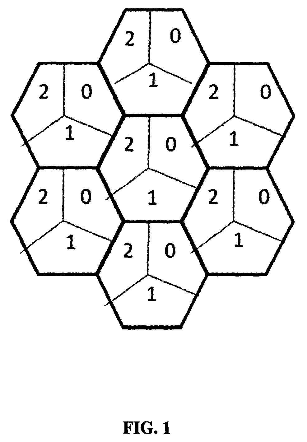
[0063]A wireless network generally comprises of many smaller cells. Each cell is further divided in to multiple sectors. Each cell / sector may have a base station (BS) and multiple mobile stations (MSs). Cellular system with 3-sectors per cell is depicted in FIG. 1. The MSs in a sector may be fi...


PUM


Abstract

Embodiments herein provide methods and systems for enhancing interference mitigation using conjugate symbol repetition and phase randomization on a set of subcarriers. The repeated data tone in the signal is complex-conjugated before transmission, when the repetition factor is two. When the repetition factor is greater than two, a combination of conjugate repetition and random / deterministic phase variation of the repeated tones is used to mitigate the interference mitigation. Embodiments further disclose Collision Free Interlaced Pilot PRU Structures that can be used with or without conjugate symbol repetition and phase randomization for interference mitigation.

Description

FIELD OF INVENTION[0001]The embodiments herein generally relate to wireless communication, and, more particularly, to enhancing interference mitigation in wireless communications.BACKGROUND AND PRIOR ART[0002]Since spectrum is a scarce resource and limited, and therefore, most of the current and emerging broadband wireless networks are expected to re-use the available spectrum in every sector / cell. Therefore, the performance of these types of systems will be limited by co-channel interference caused due to the frequency re-use mechanism. Especially in the existing IEEE 802.16e networks, the cell coverage is mainly limited by the downlink control channel (DL-MAP) coverage. It is determined by the ability of the users to correctly decode the DL-MAP, which carries essential control information such as downlink (DL) allocation and uplink (UL) grant, Multiple Input, Multiple Output (MIMO) schemes, redundancy version for Hybrid Automatic Request (HARQ), pilot format for data resource bloc...

Claims


Application Information

Patent Timeline
Patent Type & Authority Patents(United States)
IPC IPC(8): H04L5/00H04W4/00H04L27/26H04L25/03H04L25/02
CPCH04L5/0023H04L27/2621H04L25/023H04L25/03866H04L25/0204H04L27/2602H04L5/0037H04L5/0032H04L5/0048H04L25/021H04L25/025
Inventor KUCHI, KIRAN KUMARJENISTON, DEVIRAJ KLUTTO MILLETHRAMASWAMY, VINODDHIVAGAR, BASKARANGIRIDHAR, KRISHNAMURTHIRAMAMURTHI, BHASKARSURYASARMAN, PADMANABHAN MADAMPUKALATHIL, DILEEP MANISSERI
Owner CENT OF EXCELLENCE & WIRELESS TECH
Why Eureka
Try Eureka