Single-antenna direction finding system for multi-rotor platforms

a single-antenna direction and multi-rotor technology, applied in vehicle position/course/altitude control, process and machine control, instruments, etc., can solve the problems of inability to integrate with a multi-rotor uav (unmanned aerial vehicle) platform with a df algorithm, bulky systems, and inability to accurately locate the coordinates of the rf transmitter

Inactive Publication Date: 2014-12-09
KING FAHD UNIVERSITY OF PETROLEUM AND MINERALS
View PDF20 Cites 27 Cited by
  • Summary
  • Abstract
  • Description
  • Claims
  • Application Information

AI Technical Summary

Benefits of technology

[0008]The single-antenna direction finding system includes a single element directional antenna which mounts on a multi-rotor UAV (Unmanned Aerial Vehicle) and integrates with the DF (direction finding) algorithm for tracking an RF (radio frequency) source in the 2.45 GHz ISM band (or any other frequency band). The algorithm will depend on the rotating nature of the platform to scan the azimuth, as well as several elevation angles with respect to the platform axis of rotation, and thus be able to accurately locate the coordinates of the RF transmitter based on the recorded power levels. The RF source determination step is performed during the search mode of the algorithm. The RF transmitter location is saved, and the UAV takes actions accordingly by commencing movement towards that location in the action mode of the algorithm. After some time, the UAV enters the search mode again in case the RF source has moved.

Problems solved by technology

These systems were bulky and consumed too much power, and in some cases, were impractical due to mobility related issues.
Although several antenna array designs have been investigated in literature; none have actually been integrated within a multi-rotor UAV (Unmanned Aerial Vehicle) platform with a DF algorithm.

Method used


Image

  • Single-antenna direction finding system for multi-rotor platforms
  • Single-antenna direction finding system for multi-rotor platforms
  • Single-antenna direction finding system for multi-rotor platforms

Examples


Embodiment Construction

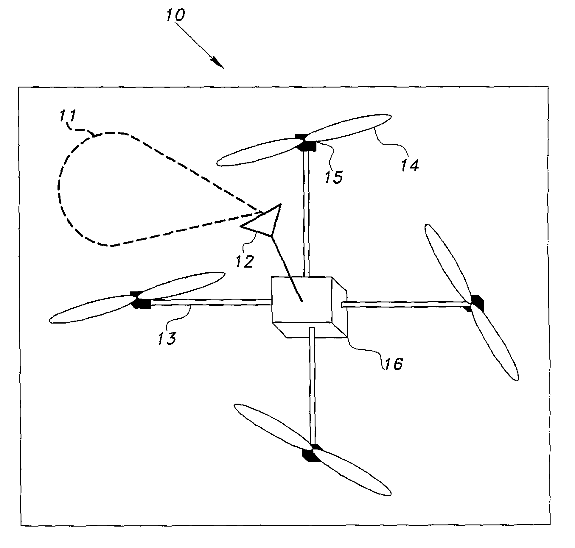
[0024]As shown in FIG. 1, the single-antenna direction finding system 10 for multi-rotor platforms includes a multi-rotor platform that has four structural arms 13 extending therefrom and a rotor attached to each arm 13, thereby forming a quad-rotor UAV (Unmanned Aerial Vehicle). Control electronics 16 are operably connected to the quad-rotor. A motor 15 and a propeller 14 are mounted at the end of each of these arms 13. The control electronics 16 will control the speed rates of the various motors 15 to cause the movement of the quad-rotor platform. A special control circuit is integrated within the control electronics 16 to perform the RF DF task. In addition, a special directive antenna 12 with a relatively narrow half-power-beam-width (HPBW) 11 is to be used for this task.

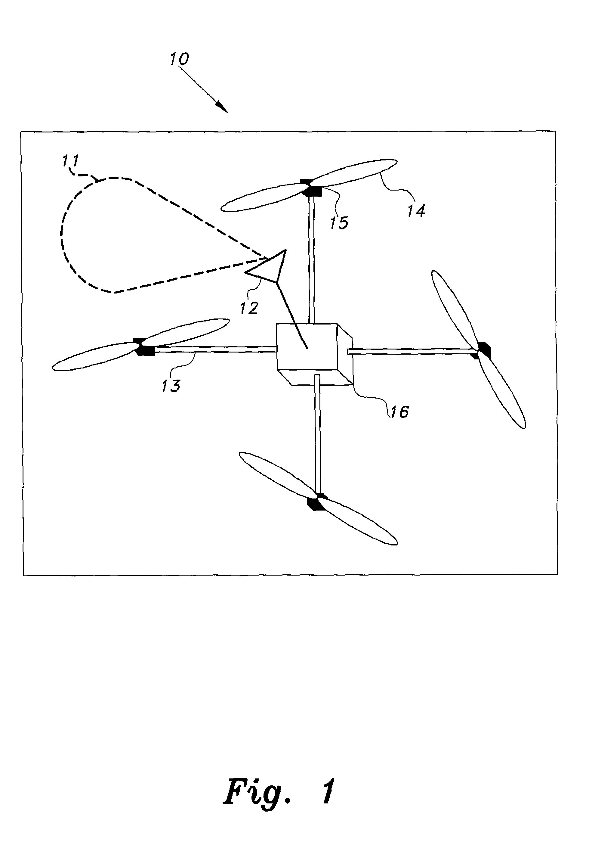
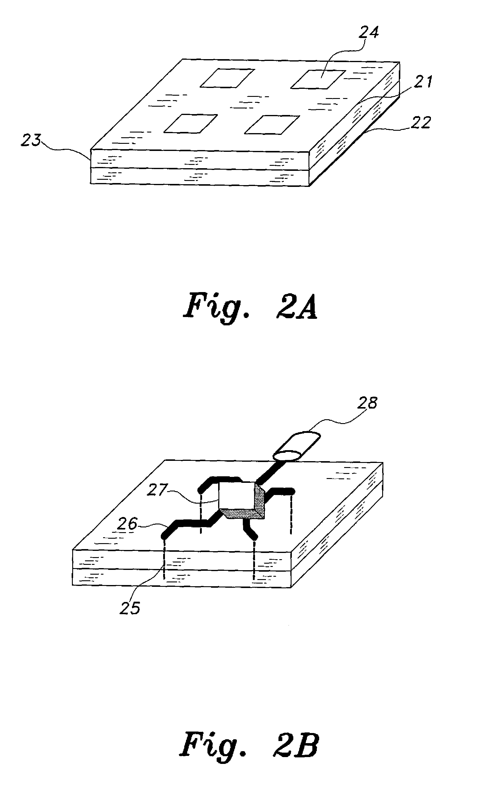
[0025]The detailed structure of the single directive antenna is shown in FIGS. 2A and 2B. An exemplary antenna internal structure includes 4-element planar antenna array comprised of printed patch antenna elemen...


PUM


Abstract

The single-antenna radio frequency (RF), direction finding (DF) system includes a single-element directional antenna, which is mounted on a multi-rotor UAV (Unmanned Aerial Vehicle) and integrates with a DF algorithm for tracking an RF source in the 2.45 GHz ISM band (or any other frequency band). The algorithm will depend on the rotating nature of the platform to scan the azimuth, as well as several elevation angles with respect to the platform axis of rotation, and thus be able to accurately locate the coordinates of the RF transmitter based on the recorded power levels. The RF source determination step is performed during the search mode of the algorithm. The RF transmitter location is saved, and the UAV takes actions accordingly by commencing movement towards that location in the action mode of the algorithm. After some time, the UAV enters the search mode again in case the RF source has moved.

Description

BACKGROUND OF THE INVENTION[0001]1. Field of the Invention[0002]The present invention relates to radio frequency direction finding systems, and particularly to a single-antenna direction finding system for multi-rotor platforms.[0003]2. Description of the Related Art[0004]Radio frequency (RF) direction finding (DF) systems are used to detect the presence of a desired / undesired RF signal transmitter location. In early systems, this process involved mechanically rotating the directional antenna across the 360° azimuth plane to find the most probable direction of the RF transmission. If the transmitted signal duration is long enough, its position can be located quite accurately.[0005]The majority of the initial RF DF antenna systems used multiple channel receiver systems, where every antenna element on the antenna array had a corresponding receiver. These systems were bulky and consumed too much power, and in some cases, were impractical due to mobility related issues. Recent advances ...

Claims


Application Information

Patent Timeline
Patent Type & Authority Patents(United States)
IPC IPC(8): G01S3/38G05D1/08G01S5/02
CPCG05D1/08G01S3/38G05D1/0094
Inventor SHARAWI, MOHAMMAD S.SABABHA, BELAL H.ALZU'BI, HAMZEH M.RAWASHDEH, OSAMAH AHMAD
Owner KING FAHD UNIVERSITY OF PETROLEUM AND MINERALS
Why Eureka
Try Eureka