Neurostimulation system for defining a generalized ideal multipole configuration

a multi-pole configuration and neurostimulation technology, applied in the field of tissue stimulation systems, can solve the problems of limited number of fractionalized electrodes, substantial amount of time and effort, and the difference between effective and ineffective pain therapy

Inactive Publication Date: 2014-12-09
BOSTON SCI NEUROMODULATION CORP
View PDF21 Cites 69 Cited by
  • Summary
  • Abstract
  • Description
  • Claims
  • Application Information

AI Technical Summary

Problems solved by technology

However, the number of electrodes available, combined with the ability to generate a variety of complex stimulation pulses, presents a huge selection of stimulation parameter sets to the clinician or patient.
Thus, correct lead placement can mean the difference between effective and ineffective pain therapy.
While the use of navigation tables have proven to be useful in steering electrical current between electrodes in an efficient manner, that are certain inherent disadvantages associated with navigation tables.
However, due to memory and time constraints, only a limited number of fractionalized electrode configurations are stored within the navigation table.
Furthermore, a substantial amount of time and effort must be spent in developing navigation tables for each new lead design, thereby presenting a bottleneck for lead development.
Because the implementation of new navigation tables must take into account all leads that are to be used with the IPG, as well as the different lead positions, this challenge slows the ability to include new navigation features in the system.
Furthermore, if the remote control needs to be reprogrammed; for example, if the patient returns to a physician's office to be refitted to improve the stimulation therapy provided by the neurostimulator, the clinician may have to start the fitting from scratch.
In particular, while the remote control is capable of uploading the stimulation parameter sets to the Bionic Navigator® to aid in reprogramming the remote control, they may be different from any stimulation parameter sets that are capable of being generated using the navigation table due to the limited number of fractionalized electrode configurations within the navigation table; that is, the fractionalized electrode configurations currently stored in the remote control may not match any fractionalized electrode configurations stored in the navigation table because they were originally generated when the Bionic Navigator® was operated in the manual mode.
In any event, if the stimulation parameter sets uploaded from the remote control to the Bionic Navigator® do not identically match any stimulation parameter set corresponding to a fractionalized electrode configuration stored in the navigation table, it cannot be used as a starting point in reprogramming the remote control / IPG.
Because programming the remote control can be quite complex, even when the Bionic Navigator® is operated in the navigation mode, the time lost as a result of having to reprogram the remote control / IPG from scratch, can be quite significant.
For example, ideal target poles aligned along the longitudinal axis of the spinal cord of a patient may be optimum when steering current in a rostro-caudal (longitudinal) direction, but may not be optimum when steering current in a medial-lateral (transverse) direction.
Likewise, ideal target poles aligned perpendicular to the longitudinal axis of the spinal cord of a patient may be optimum when steering current in a medial-lateral (transverse) direction, but may not be optimum when steering current in a rostro-caudal direction (longitudinal).
Furthermore, because there a limited number of electrodes when steering current in a particular direction using arbitrarily defined target poles, there remains a need to modify the current steering on-the-fly to prevent any target poles from being moved outside the maximum extent of the electrode array.
However, because different types of neurostimulation leads have different electrode separations, a current steering algorithm that is designed for a particular electrode separation cannot be used for other electrode separations.
Furthermore, when multiple neurostimulation leads are used, the spacings between the electrodes will typically not be uniform, thereby providing a challenge when attempting to match the ideal cathode / anode spacings with the spacings of the physical electrodes.

Method used


Image

  • Neurostimulation system for defining a generalized ideal multipole configuration
  • Neurostimulation system for defining a generalized ideal multipole configuration
  • Neurostimulation system for defining a generalized ideal multipole configuration

Examples


Embodiment Construction

[0069]The description that follows relates to a spinal cord stimulation (SCS) system. However, it is to be understood that while the invention lends itself well to applications in SCS, the invention, in its broadest aspects, may not be so limited. Rather, the invention may be used with any type of implantable electrical circuitry used to stimulate tissue.

[0070]For example, the present invention may be used as part of a pacemaker, a defibrillator, a cochlear stimulator, a retinal stimulator, a stimulator configured to produce coordinated limb movement, a cortical stimulator, a deep brain stimulator, peripheral nerve stimulator, microstimulator, or in any other neurostimulator configured to treat urinary incontinence, sleep apnea, shoulder sublaxation, headache, etc.

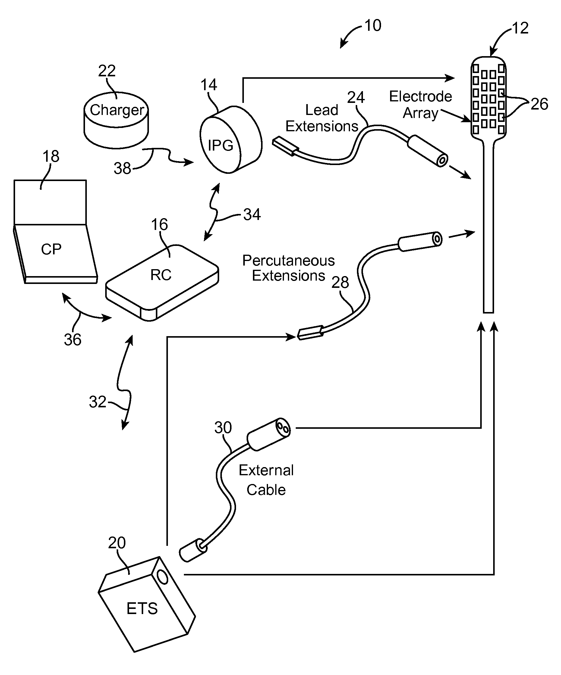
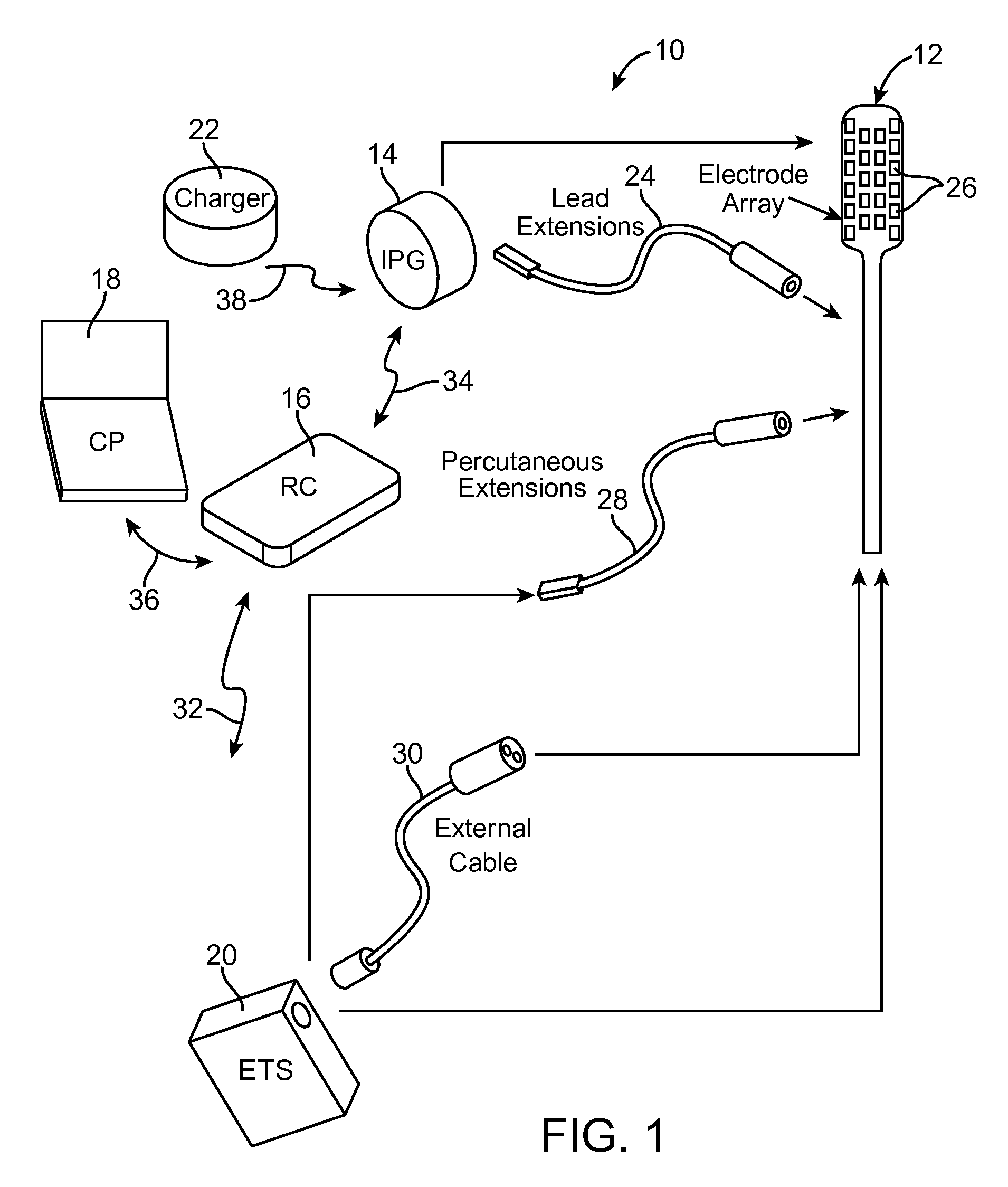
[0071]Turning first to FIG. 1, an exemplary SCS system 10 generally comprises at least one implantable neurostimulation lead 12, an implantable pulse generator (IPG) 14 (or alternatively RF receiver-stimulator), an externa...


PUM


Abstract

A system for a neurostimulator coupled to electrodes. The system comprises an input device configured for generating control signals. The system further comprising memory storing a first set of variable values defining a first spatial relationship between a central ideal pole of a first polarity and the plurality of electrodes, a second set of variable values defining a second spatial relationship respectively between four ideal poles of a second polarity and the first ideal pole, and a third set of variable values defining relative intensities between the four ideal poles. The system further comprises control circuitry configured for modifying the first variable values, the second variable values, and / or the third variable values, and generating stimulation parameter values defining relative amplitude values for the electrodes that emulate the ideal poles, and instructing the neurostimulator to convey electrical energy to the electrodes in accordance with the stimulation parameter values.

Description

RELATED APPLICATIONS[0001]The present application claims the benefit under 35 U.S.C. §119 to U.S. Provisional Patent Application Ser. No. 61 / 452,965, filed Mar. 15, 2011. The foregoing application is hereby incorporated by reference into the present application in its entirety. The present utility application is filed concurrently with U.S. patent application Ser. No. 13 / 420,040, entitled “NEUROSTIMULATION SYSTEM AND METHOD FOR ROSTRO-CAUDALLY STEERING CURRENT”, U.S. patent application Ser. No. 13 / 420,209, entitled “NEUROSTIMULATION SYSTEM AND METHOD FOR MEDIO-LATERALLY STEERING CURRENT USING IDEAL MULTIPOLE CONFIGURATIONS”, U.S. patent application Ser. No. 13 / 420,258, entitled “NEUROSTIMULATION SYSTEM FOR DEFINING IDEAL MULTIPOLE CONFIGURATIONS AT LEAD BOUNDARY”, and U.S. patent application Ser. No. 13 / 420,312, entitled “NEUROSTIMULATION SYSTEM FOR MATCHING IDEAL POLE SPACING WITH EFFECTIVE ELECTRODE SEPARATION, the disclosures of which are expressly incorporated herein by referenc...

Claims


Application Information

Patent Timeline
Patent Type & Authority Patents(United States)
IPC IPC(8): A61N1/36A61N1/372
CPCA61N1/36185A61N1/37247
Inventor LEE, DONGCHUL
Owner BOSTON SCI NEUROMODULATION CORP
Why Eureka
Try Eureka