Fluid controller

a controller and flue technology, applied in the direction of valve housings, hose connections, instruments, etc., can solve the problems of easy damage to the casing, difficulty in achieving a sufficiently high level of processing precision, and sensitivity drop, so as to reduce the width-direction dimension of the casing, maintain the mechanical strength of the casing, and reduce the level of sensitivity

Active Publication Date: 2014-12-16
HORIBA STEC CO LTD
View PDF30 Cites 20 Cited by
  • Summary
  • Abstract
  • Description
  • Claims
  • Application Information

AI Technical Summary

Benefits of technology

[0018]According to an aspect of the present invention configured as described above, it is possible to further pursue miniaturization of fluid controllers by drastically reducing the width-direction dimension from conventional examples without lowering the level of sensitivity in pressure measuring processes and by reducing the width-direction dimension of the casing while also maintaining the mechanical strength of the casing.

Problems solved by technology

However, in conventional mass flow controllers, because the pressure sensors are positioned so that the pressure sensing surfaces thereof extend parallel to the component part attachment face of the body, if we try to further reduce the width-direction dimension of the entire mass flow controller, the areas of the pressure sensing surfaces become smaller, which may lead to a decrease in the sensitivity.
This is a bottleneck in the endeavor to make mass flow controllers compact and, especially, to reduce the size in the width direction.
However, this method has a problem where it is difficult to achieve a sufficiently high level of precision in the processing and where the casing is easily damaged due to an insufficient mechanical strength thereof.

Method used


Image

  • Fluid controller
  • Fluid controller
  • Fluid controller

Examples


Embodiment Construction

[0035]Exemplary embodiments of a fluid controller according to the present invention will be explained below, with reference to the accompanying drawings.

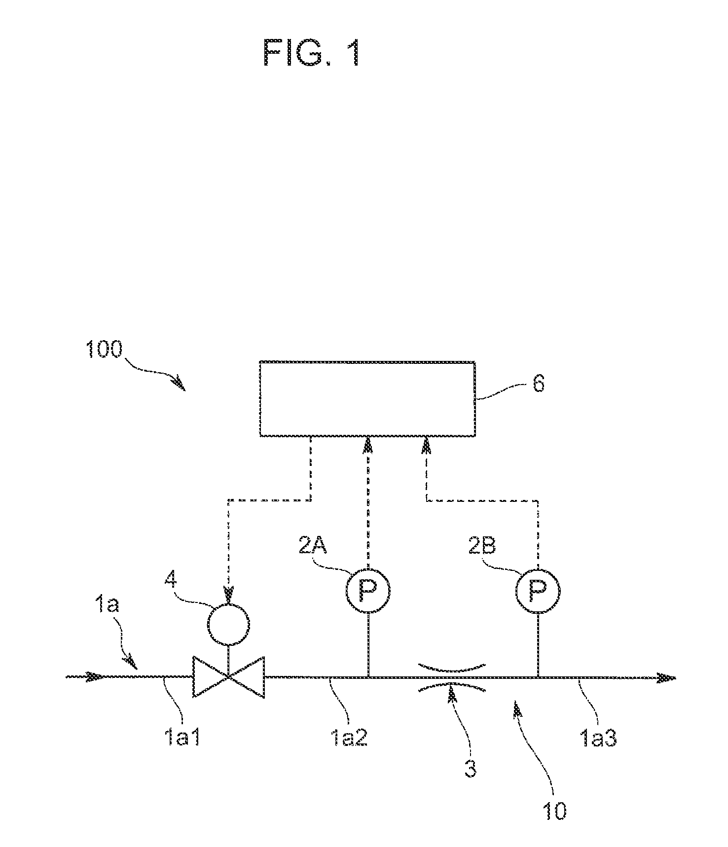
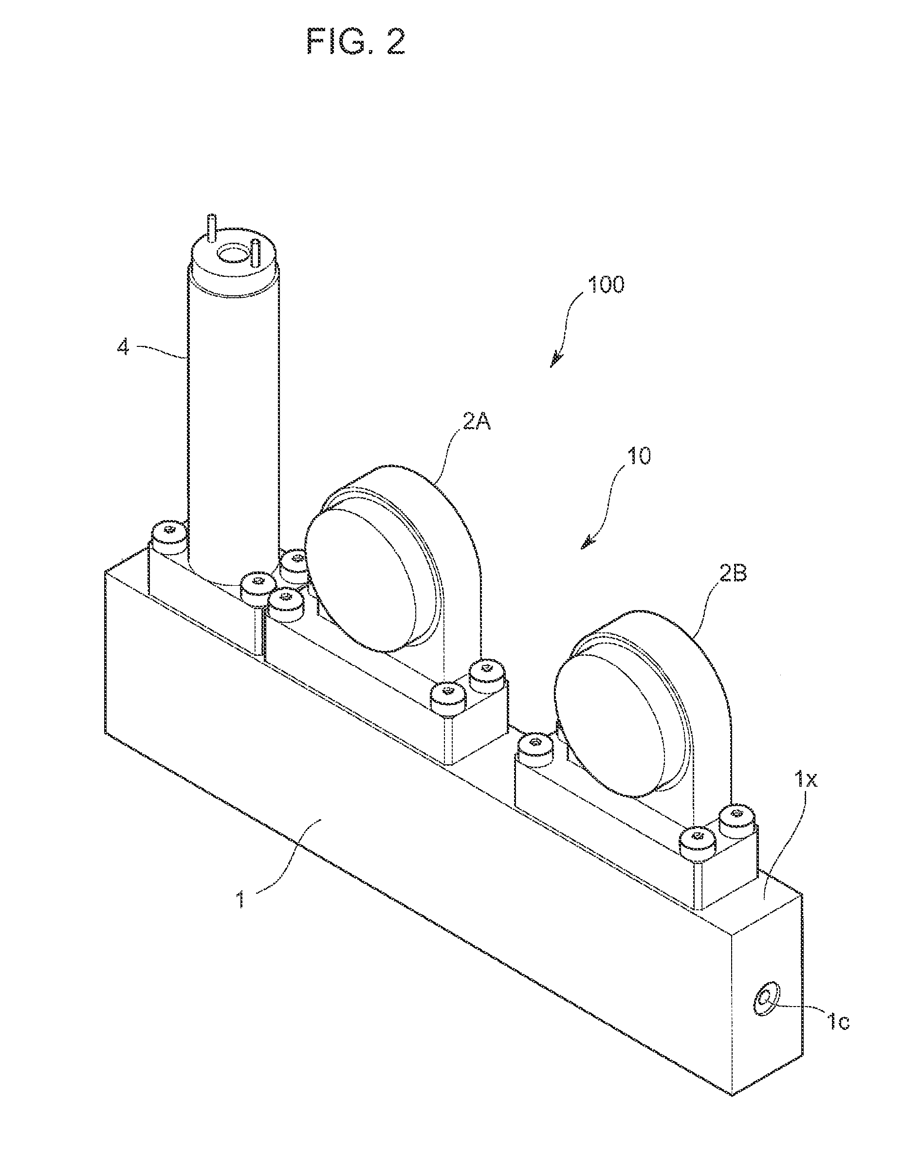
[0036]A fluid controller 100 according to an embodiment may be installed on a gas panel, for example, and may constitute a part of a material supply line for a semiconductor manufacturing apparatus. As shown in the fluid circuit diagram in FIG. 1 and the overall perspective view in FIG. 2, the fluid controller 100 is a mass flow controller including: a body unit 1 having an internal flow path 1a through which fluid serving as a target of flow-rate control flows; a flow rate adjusting valve 4 that is provided in the internal flow path 1a and serves as a fluid controlling valve; a flow rate measuring mechanism 10 that is provided on the downstream side of the flow rate adjusting valve 4 and measures a mass flow rate of the fluid flowing through the internal flow path 1a; and a controlling circuit 6 (not shown in FIG. 2) that controls...


PUM


Abstract

A fluid controller is disclosed, having a body unit, a fluid controlling valve, pressure sensors, and a casing. The fluid controlling valve is attached to a component part attachment face of the body unit. The pressure sensors are attached to the component part attachment face so that the pressure sensing surfaces thereof are positioned substantially perpendicular to the component part attachment face and substantially parallel to the longitudinal direction. On the lateral walls of the casing, the inner surfaces thereof are arranged to be uneven, so that such sections facing the fluid controlling valve and the pressure sensors are arranged to be thin sections, whereas at least a part of such a section that does not face the fluid controlling valve and the pressure sensors is arranged to be a thick section that is thicker than the thin sections.

Description

TECHNICAL FIELD[0001]The present invention relates to a fluid controller that controls the pressure and / or the flow rate of a raw material gas or the like used in a semiconductor process.BACKGROUND ART[0002]As indicated in Patent Document 1, as a pressure sensor used in a flow rate measuring mechanism or a mass flow controller of this type, a pressure sensor is known that is configured to receive the pressure of fluid on a pressure sensing surface provided on a diaphragm or the like and to measure the fluid pressure on the basis of a positional change of the pressure sensing surface. For pressure sensors using this method, the larger the area of the pressure sensing surface of the pressure receiving member is, the higher the level of sensitivity is.[0003]Examples of conventional mass flow controllers include one in which a pressure sensor and a flow rate adjusting valve are attached to a body that has formed therein a flow path through which a control-target fluid flows. In recent y...

Claims


Application Information

Patent Timeline
Patent Type & Authority Patents(United States)
IPC IPC(8): G05D7/06F16K27/12F16K31/02G05D7/01
CPCG05D7/0635G05D7/0106Y10T137/7762Y10T137/7062Y10T137/7043Y10T137/7759Y10T137/7761
Inventor YASUDA, TADAHIRO
Owner HORIBA STEC CO LTD
Why Eureka
Try Eureka