
Temperature detector for a contact thermometer

a temperature detector and thermometer technology, applied in the direction of resistor details, resistors using electrical/magnetic means, resistors, etc., can solve the problems of difficult handling and relatively expensive temperature detectors known from the prior art, and achieve the effect of simple and economical construction

Active Publication Date: 2014-12-16
INOR PROCESS
View PDF27 Cites 12 Cited by
  • Summary
  • Abstract
  • Description
  • Claims
  • Application Information

AI Technical Summary

Benefits of technology

The present invention provides a temperature detector with a simple and economical construction, which can be used for mass applications in a comparably low temperature range, such as up to 300°C. The detector uses a connection printed circuit board with conducting paths for the electrical connecting means, which simplifies mounting and makes the detector more economical compared to known implementations. The connection printed circuit board can be made of printed circuit boards with different materials, such as phenol or epoxy resin, polytetrafluoroethylene, or ceramic. The design also allows for the use of an economical printed circuit board material for the contact printed circuit board, which is constantly stable at lower temperatures. This further reduces costs and allows for the use of more economical printed circuit board materials. The connection printed circuit board can be positioned in the middle of the thermowell to minimize the contact surfaces between the two.

Problems solved by technology

Temperature detectors known from the prior art are relatively expensive, which, on the one hand, is due to the relatively complex production, and on the other hand, however, due to the materials being used.
Apart from the electrical connecting means with mineral insulation being expensive, they are also difficult to deal with in production, since it is necessary to make sure that the mineral powder remains in contact when mounting the thermal sensor element, which is difficult for thermowell diameters having only few millimeters to fractions of a millimeter and is practically not applicable for automation.

Method used


Image

  • Temperature detector for a contact thermometer
  • Temperature detector for a contact thermometer
  • Temperature detector for a contact thermometer

Examples


Embodiment Construction

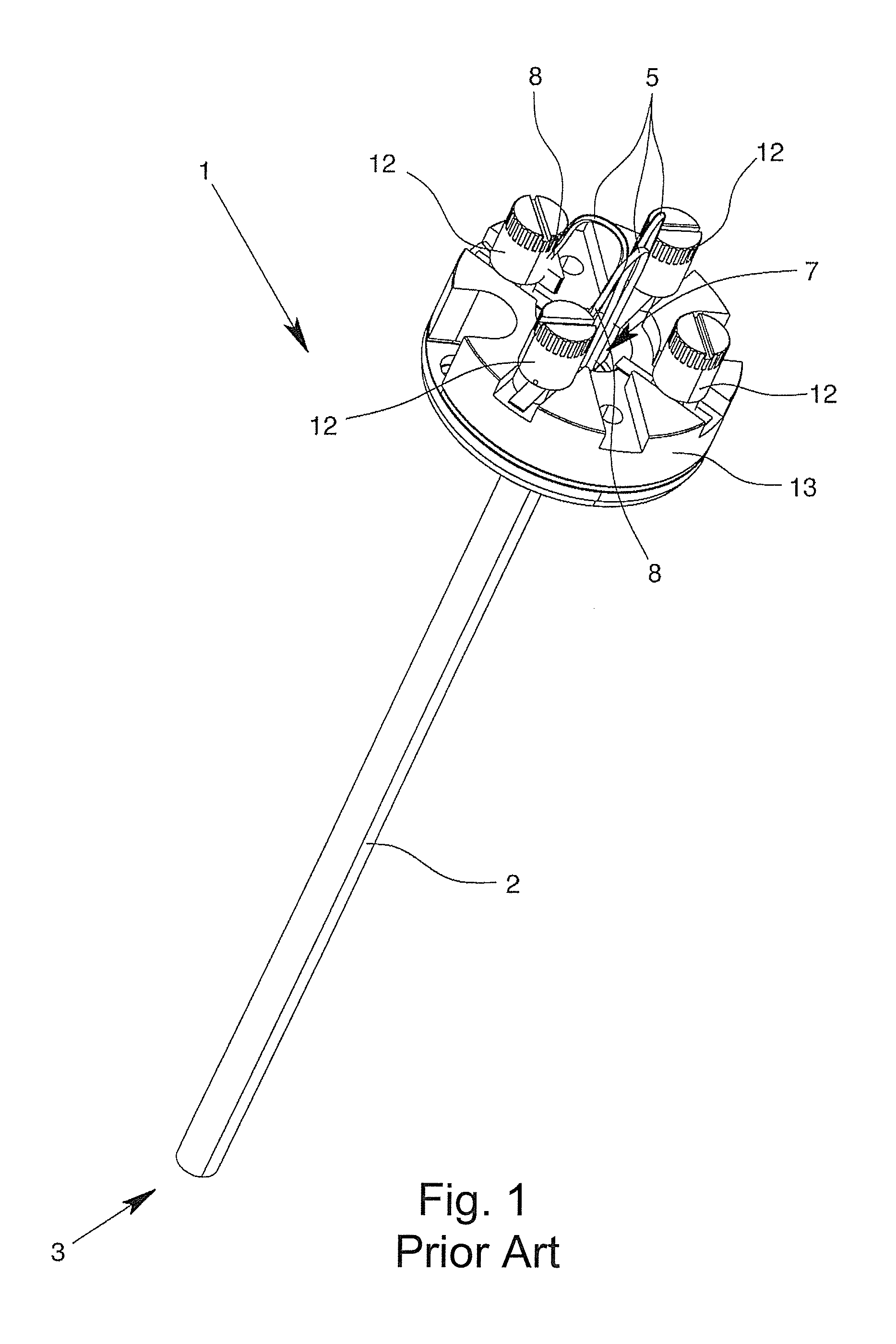
[0026]A temperature detector 1 known from the prior art is shown in FIG. 1, which is intended for contact thermometers of process measurement technology. The temperature detector 1 has a thermowell 2, in which a thermal sensor element is arranged on the process-side end 3 (not shown in FIG. 1), which is provided with reference numbers in FIGS. 4 & 6.

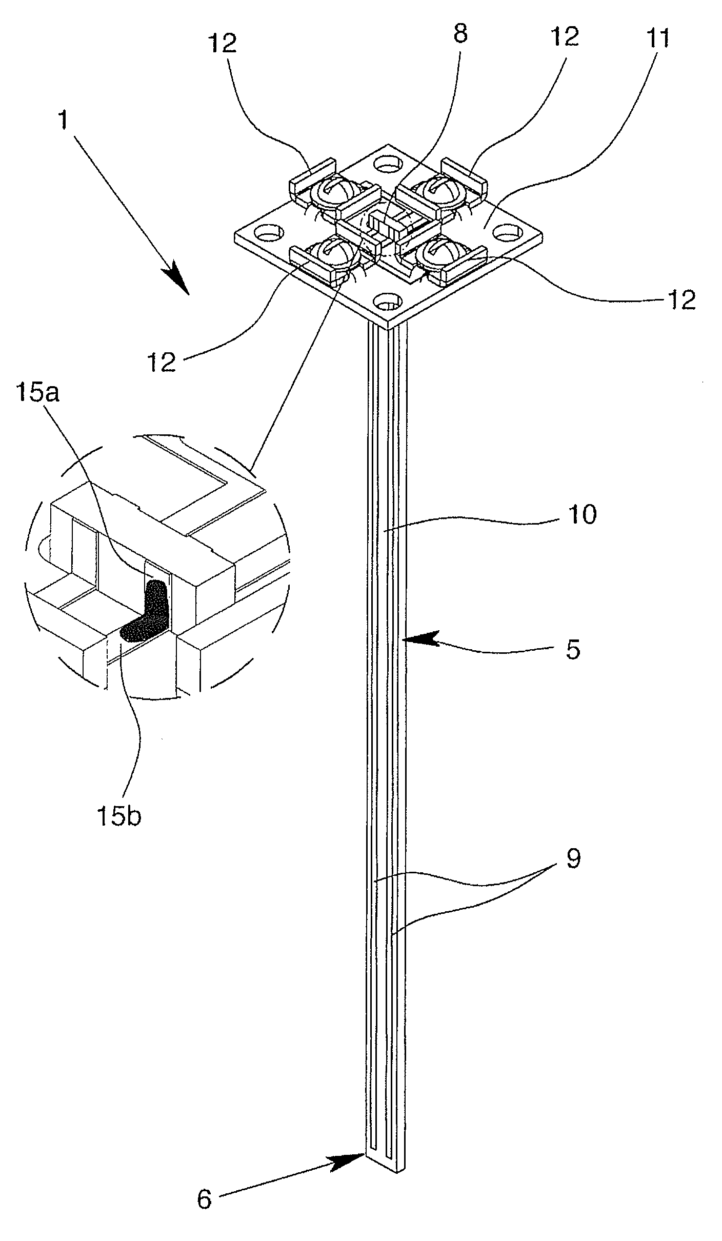
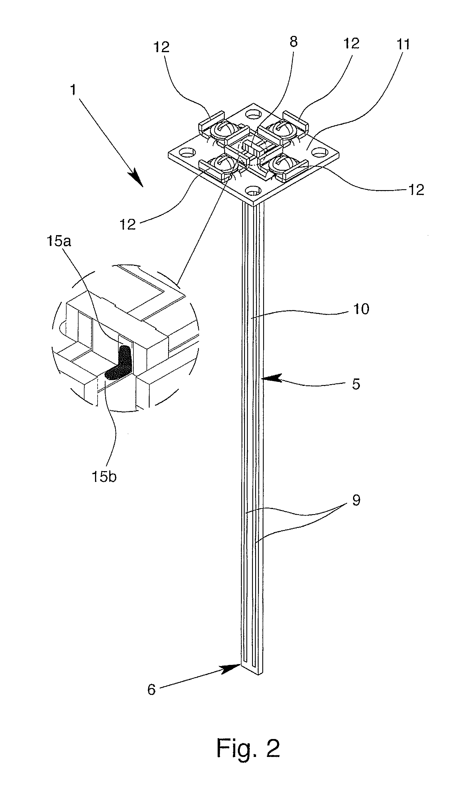
[0027]The temperature detector 1 further has electrical leads as electrical connecting means 5, wherein this electrical connecting means 5—as can be seen in the version according to the invention in FIGS. 2 to 4&6—is connected to the thermal sensor element 4 with a first connection side 6. The electrical connecting means 5 then runs in the thermowell 2 to the evaluation-side end 7 of the thermowell 2, so that the thermal sensor element 4 can basically be electrically contacted via a second connection side 8 of the electrical connecting means 5. As can be seen in FIG. 1, the electrical connecting means 5 in the prior art is formed of a pl...


PUM

PropertyMeasurementUnit
temperatureaaaaaaaaaa
temperaturesaaaaaaaaaa

Abstract

A temperature detector for a contact thermometer of process measurement technology having a thermowell, at least one thermal sensor element arranged in a process-side end of the thermowell, and at least one electrical connecting means connected to the thermal sensor element with a first connection side and extending in the thermowell at least up to an evaluation-side end of the thermowell, so that the thermal sensor element can be electrically contacted via a second connection side of the electrical connecting means, and in which the electrical connecting means is formed by a connection printed circuit board with conducting paths.

Description

BACKGROUND OF THE INVENTION[0001]1. Field of the Invention[0002]The invention relates to a temperature detector for a contact thermometer of process measurement technology having a thermowell, at least one thermal sensor element arranged in the process-side end of the thermowell and at least one electrical connecting means, wherein the electrical connecting means is connected to the thermal sensor element with a first connection side and extends in the thermowell at least up to the evaluation-side end of the thermowell, so that the thermal sensor element can be electrically contacted via a second connection side of the electrical connecting means.[0003]2. Description of Related Art[0004]Temperature detectors of the above mentioned type have been known for a long time in practice, wherein temperature detectors of this type come directly or indirectly into contact with the medium of which the temperature is to be determined. Contact thermometers should be presently differentiated from...

Claims


Application Information

Patent Timeline
Patent Type & Authority Patents(United States)
IPC IPC(8): G01K1/14G01K1/08G01K1/16G01K7/16H01C1/14
CPCG01K1/08G01K1/14
Inventor MARTENSSON, HANS-OWE
Owner INOR PROCESS
Learn More