Dual-derrick ice-worthy jack-up drilling unit

a drilling unit and dual-derrick technology, applied in floating buildings, ice breakers, artificial islands, etc., can solve the problems of large, undiscovered resources remain to be found, new large reserves are being found in more challenging and difficult-to-reach areas, and the drilling potential is larg

Inactive Publication Date: 2014-12-16
CONOCOPHILLIPS CO +1
View PDF11 Cites 8 Cited by
  • Summary
  • Abstract
  • Description
  • Claims
  • Application Information

AI Technical Summary

Benefits of technology

[0014]For some embodiments, the flotation hull includes an ice bending shape along the lower portion thereof and extending around a periphery of the flotation hull. The ice-bending shape extends from an area of the hull near the level of the deck or the bottom thereof and extends downwardly and tapers inwardly near the bottom. The ice hull can double or triple the drilling season, and thus is of tremendous value.
[0019]The jack-up rig further comprises at least two derricks mounted on the deck. The derricks are positioned at the same side, or preferably opposite sides of the deck for improved balance. In the case where the two derricks are positioned at the same side of the deck, an additional balancing means can be provided at the opposite side of the deck opposing the two derricks, but may not be needed if a single balance means is properly positioned between the two. In this embodiment, at least four legs can be employed. The dual derrick system doubles the drilling potential of the rig, particularly when direction drilling is employed.
[0022]At least three legs are positioned inside the perimeter of the hull. Each leg is jacked down so that the legs engage the sea floor and lift the hull up and fully out of the water when ice is not threatening the rig. The ice hull also can be lowered into the water into an ice defensive configuration so that the ice bending shape extends both above and below the sea surface to bend and breaks any ice that floats against the rig. Drilling from the dual derricks can occur during either of these stages, and thus drilling potential is at least 400-600% improved over single derrick, skirt-less rig designs, particularly when directional drilling in different directions on the two derricks is employed.

Problems solved by technology

Few expect that any large, undiscovered resources remain to be found near populated areas and in places that would be easily accessed.
Instead, new large reserves are being found in more challenging and difficult to reach areas.
However, the Arctic is cold, remote and ice on the water creates considerable challenges for prospecting for hydrocarbons.
Over the years, it has generally been regarded that six unprofitable wells must be drilled for every profitable well.
However, little in the Arctic is inexpensive.
Even during the few weeks of open water, ice floes present a significant hazard to jack-up drilling rigs on location and legs of the jack-up drilling rig are exposed and quite vulnerable to damage.
However, the legs of a jack-up provide little defense against ice floe collisions and an ice floe of any notable size is capable of causing structural damage to one or more legs and / or pushing the rig off location.
If this type of event were to happen before the drilling operations were suspended and suitable secure and abandon had been completed, a hydrocarbon leak would possibly occur.
Even a small risk of such a leak is completely unacceptable in the oil and gas industry, to the regulators and to the public.
These gravity-based structures are very large and very expensive, but are built to withstand the ice forces year around.
Unlike jack-up rigs, semi-submersible vessels by nature are subject to both the wave and impact of ice floe, and therefore cannot withstand the extreme conditions in the Artic.
However, this patent is also directed to a drilling ship that cannot maintain high stability required in the Artic under harsh weather conditions.
Additionally, the dual-activity drilling assembly disclosed can only drill one well at a time, which is inherently inefficient for exploration or production purposes, especially at a place where only a very narrow window of operation is available.
However, this rig is still subject to the vagaries of weather and does not solve the ice problem that exists in Artic or North sea drilling.

Method used


Image

  • Dual-derrick ice-worthy jack-up drilling unit
  • Dual-derrick ice-worthy jack-up drilling unit
  • Dual-derrick ice-worthy jack-up drilling unit

Examples


example 1

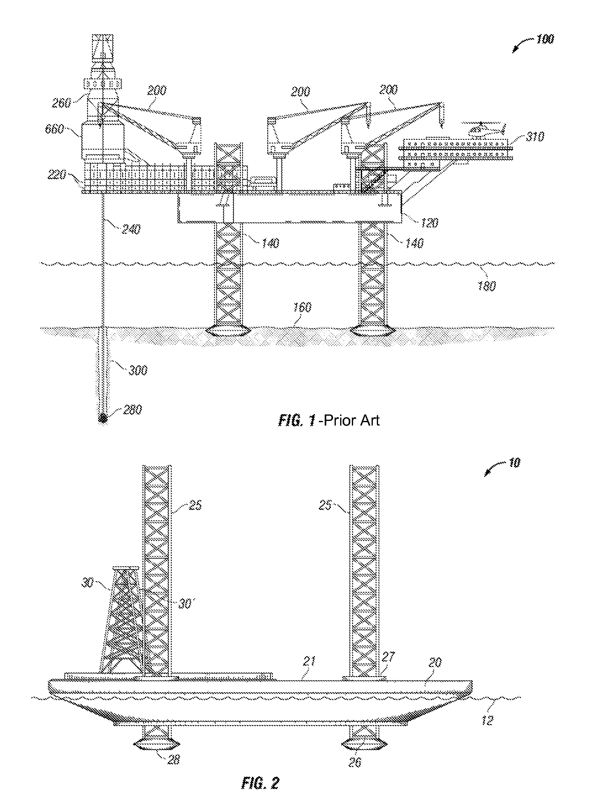
[0048]FIG. 1 is a prior art drilling rig 100 which shows a jack-up rig in more detail, including the elevated hull 120 lifted above waterline 180 via legs 140, heliport 310, cranes 200, cantilevered drill portion 220 having derrick 260 with drill floor 660, and drill string 240 descending into open hole 300 past the sea floor 160 and ending in drill bit 280. Spud cans are also shown, but not labeled. Considerable detail is omitted from this figure, including various safety and control systems, piping, crew quarters, marine equipment, mission equipment, and elevating equipment, but it can be seen that a jack-up rig has limited space and complex structure. Hereinafter, the jack-up rig figures are simplified somewhat for clarity of viewing.

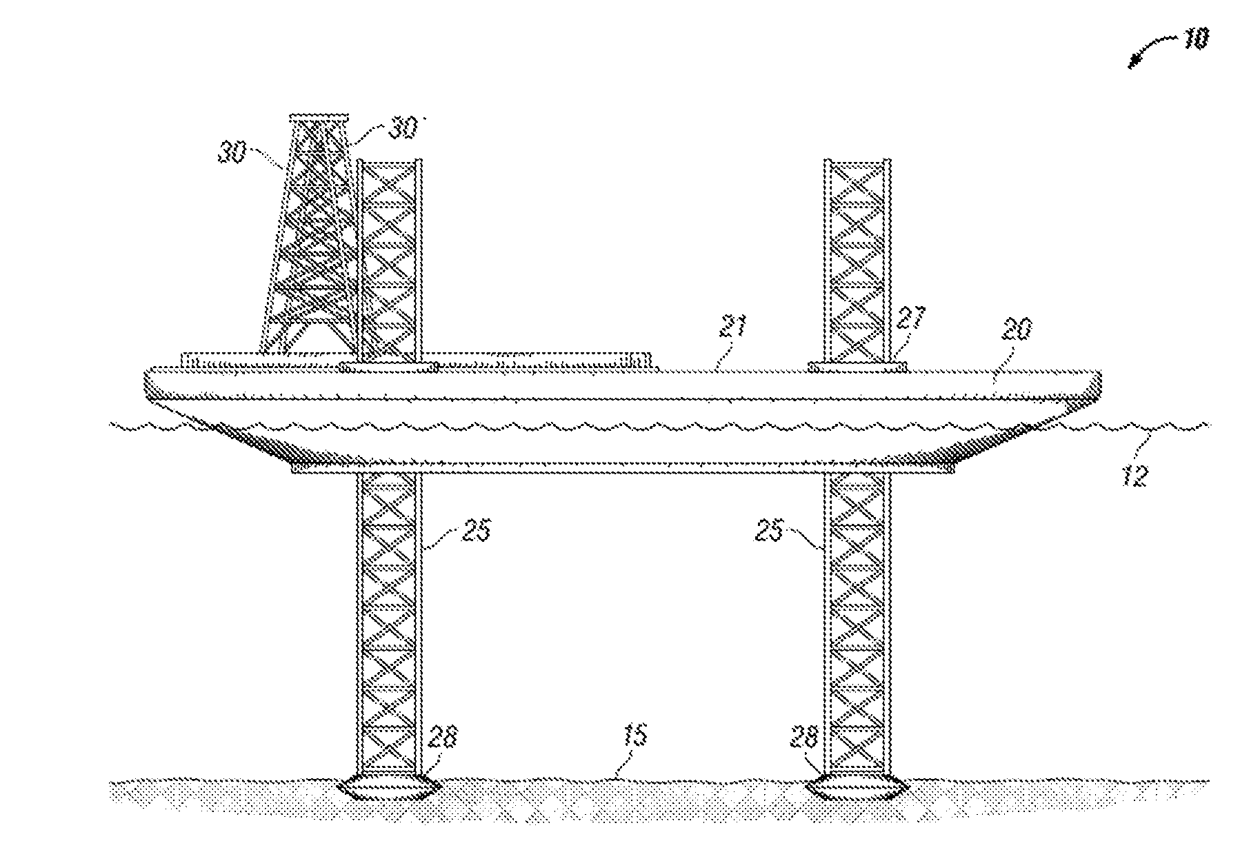
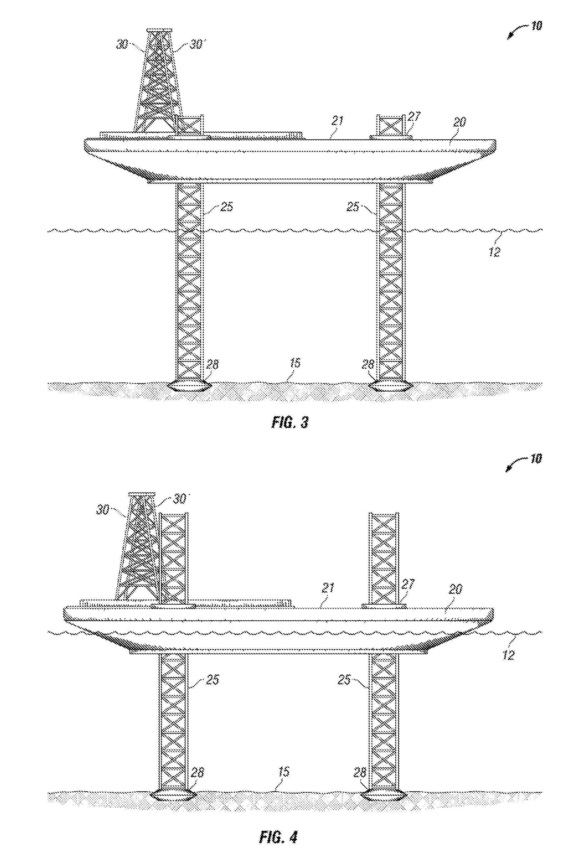
[0049]As shown in FIG. 2, an ice worthy jack-up rig is generally indicated by the arrow 10. In FIG. 2, jack-up rig 10 is shown with its hull 20 floating in the sea and legs 25 in a lifted arrangement where much of the length of the legs 25 extend abo...


PUM


Abstract

The invention relates to a jack-up rig. The inventive rig would work like a conventional jack-up rig while in open water with the hull jacked up out of the water. However, in the event of ice conditions, the hull is lowered into the water into an ice defensive configuration. The hull is specifically shaped with a lower portion that is an ice-bending surface to bend and break up ice that comes in contact with the hull while in the ice defensive configuration. Furthermore, the jack-up rig comprises at least two derricks.

Description

PRIOR RELATED APPLICATIONS[0001]This application is a continuation of International Application No. PCT / SG2011 / 000369, filed on Oct. 21, 2011, which claims priority to U.S. Application No. 61 / 405,497, filed on Oct. 21, 2010, both are incorporated by reference in their entirety herein.FIELD OF THE INVENTION[0002]This invention relates to mobile offshore drilling units, often called “jack-up” drilling units or rigs that are used in shallow water, typically less than 400 feet, for exploratory or development drilling for hydrocarbons.BACKGROUND OF THE INVENTION[0003]In the never-ending search for hydrocarbons, many technologies have been developed to find new reservoirs and resources and most areas of the world have been scoured looking for new discoveries. Few expect that any large, undiscovered resources remain to be found near populated areas and in places that would be easily accessed. Instead, new large reserves are being found in more challenging and difficult to reach areas.[0004...

Claims


Application Information

Patent Timeline
Patent Type & Authority Patents(United States)
IPC IPC(8): E02B17/00E21B7/00B63B35/08E02B17/08E02B17/02E21B15/02
CPCE02B17/021E02B17/0021E02B2017/0082E21B15/02E21B7/008E02B2017/006B63B35/08E02B2017/0039B63B35/44E02B17/00E02B17/02
Inventor NOBLE, PETER G.SHAFER, RANDALL S.BERTA, DOMINIQUE P.CHOW, YEW YUENCHEUNG, TAK ONFOO, KOK SENGQUAH, CHIN KAUWANG, CYNTHIA
Owner CONOCOPHILLIPS CO
Why Eureka
Try Eureka