Particulate matter sensor, system, and method of using a correction unit

a technology of particle matter sensor and correction unit, which is applied in the direction of using mechanical means, machines/engines, instruments, etc., can solve the problems of difficult elimination inability to ensure the detection accuracy of the output of the pm sensor, and difficulty in eliminating the influence of the temperature of the pm layer such as the temperature of around the pm sensor, so as to achieve high accuracy and high exhaust flow rate

Active Publication Date: 2014-12-23
DENSO CORP
View PDF27 Cites 17 Cited by
  • Summary
  • Abstract
  • Description
  • Claims
  • Application Information

AI Technical Summary

Benefits of technology

[0014]Thus, in the detection apparatus of the present disclosure, a pair of electrodes are arranged on an insulator. In this configuration, voltage is applied across the electrodes that have been electrically connected via the particulate matter (PM) deposited on the insulator to obtain a detection value correlated to the amount of PM in the exhaust gas. In obtaining the detection value, a PM detection value is corrected using the exhaust temperature of the exhaust gas passing through the detection unit or the insulator temperature of the insulator. Thus, a PM detection value can be corrected so as to mitigate the influence of thermal migration associated with the temperature of the detection unit or the temperature distribution around the detection unit, or the influence of change of electrical resistance. In this way, a high-accuracy detection apparatus is realized, which is able to detect the amount of PM (hereinafter also referred to as “PM amount”) in an exhaust path, without being affected by thermal migration or change of electrical resistance.
[0036]Thus, an exhaust flow rate is calculated based on an intake volume, a fuel injection quantity, the temperature in an exhaust path, and the pressure in the exhaust path of the internal combustion engine. Thus, an exhaust flow rate can be calculated with high accuracy. In this way, a detection apparatus is realized, which is able to correct a PM detection value to one having high accuracy, using a highly accurate exhaust flow rate.

Problems solved by technology

However, detection values of a PM sensor depend such as on the operating conditions of the engine and thus high accuracy is not ensured in the detection.
When the amount of PM in an exhaust pipe is desired to be obtained based on the output of a PM sensor, the influence given to the output of the PM sensor such as by the temperature of and around the PM sensor and the temperature of the PM layer is difficult to be eliminated.

Method used


Image

  • Particulate matter sensor, system, and method of using a correction unit
  • Particulate matter sensor, system, and method of using a correction unit
  • Particulate matter sensor, system, and method of using a correction unit

Examples


first embodiment

(First Embodiment)

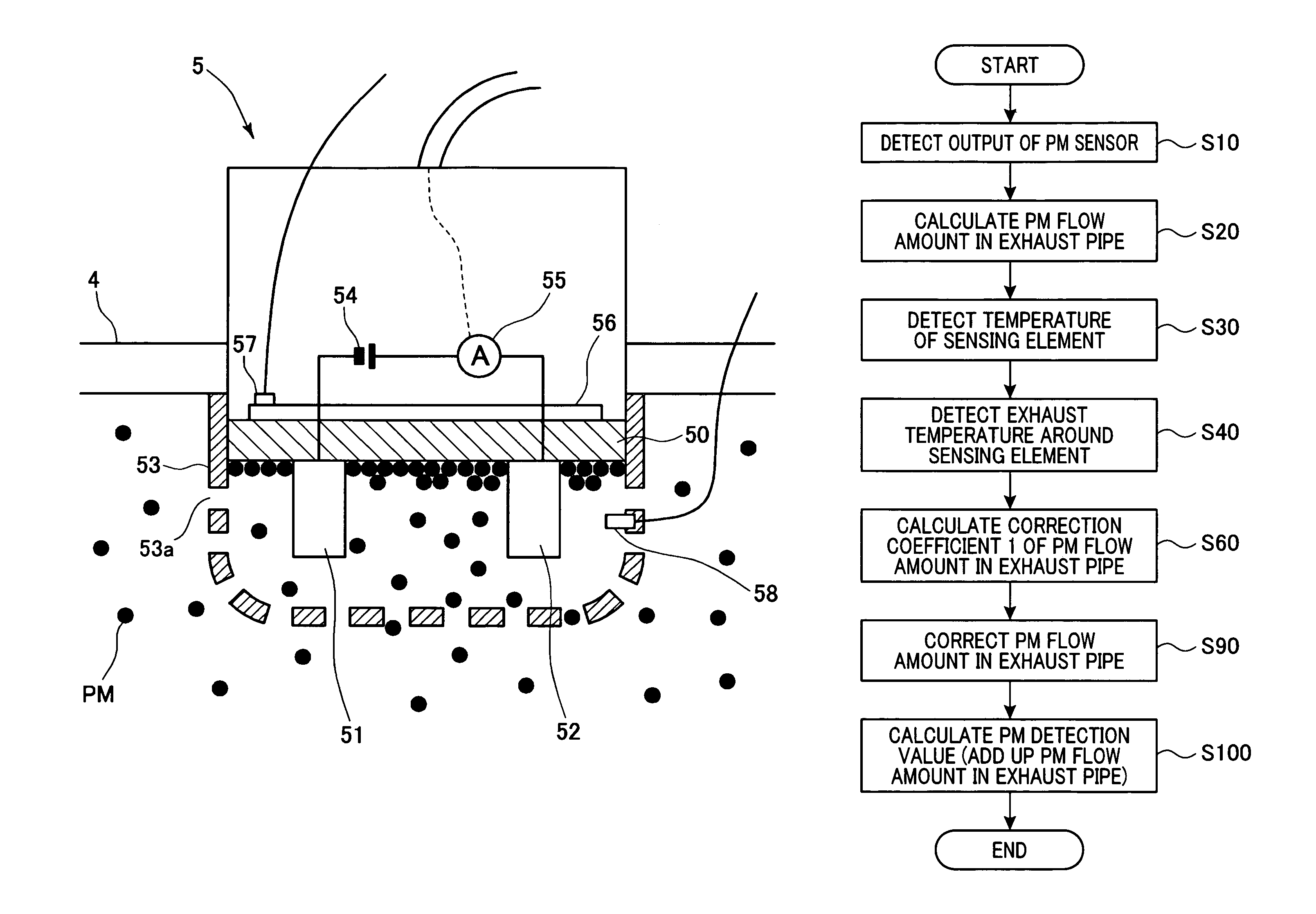
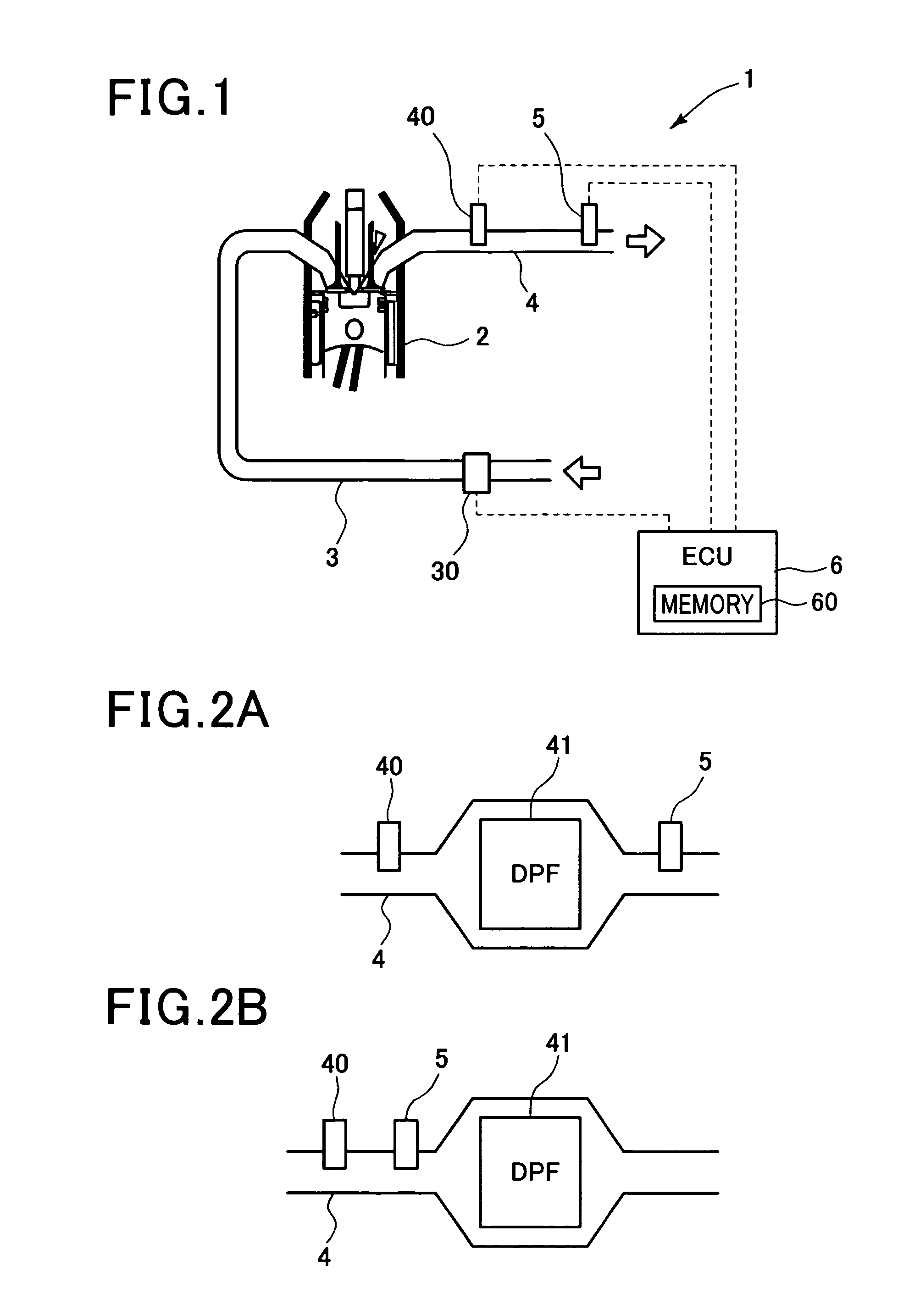
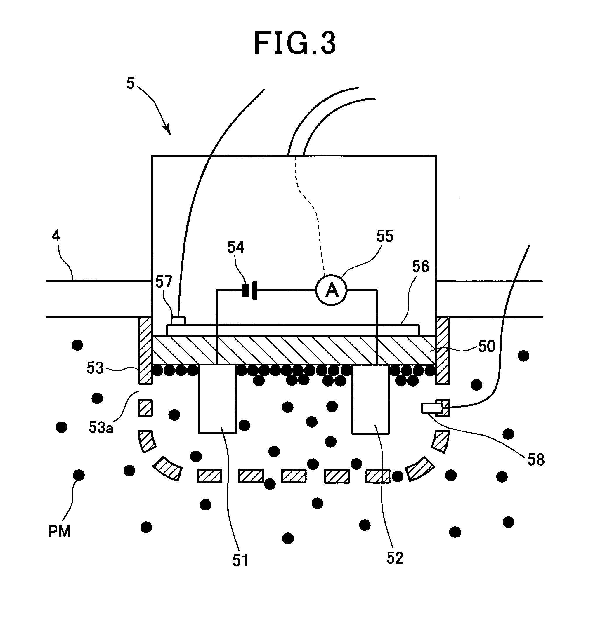
[0052]Referring first to FIGS. 1 to 4, 7 and 10 to 13, a first embodiment of the present invention is described. FIG. 1 is a schematic diagram illustrating a detection system 1 that configures a detection apparatus according to the first embodiment. The detection system 1 is used for detecting the amount of particulate matter (PM) flowing through an exhaust pipe (exhaust path) 4 (hereinafter this amount is also referred to as “PM amount”) of a diesel engine 2 (engine) that is an internal combustion engine. The detection system 1 also includes an intake pipe 3 that supplies intake gas (air) to the engine 2. The intake pipe 3 (intake path) is provided with an air flow meter 30 that detects an intake volume (e.g., mass flow rate per unit time). The exhaust pipe 4 of the engine 2 is provided with an exhaust temperature sensor 40 and a PM sensor 5.

[0053]The exhaust temperature sensor 40 detects the temperature of an exhaust gas (hereinafter also referred to as “exhaust ...

second embodiment

(Second Embodiment)

[0079]Referring now to FIGS. 5 and 8, hereinafter is described a second embodiment of the present invention. In the first embodiment described above, a PM flow amount in the exhaust pipe 4 has been corrected to eliminate the influence of thermal migration. In the second embodiment, a PM flow amount is corrected to eliminate the influence associated with exhaust flow speed, as well as the influence of thermal migration. The system configuration shown in FIGS. 1 to 3 may be used in the second embodiment.

[0080]FIG. 5 is a flow diagram illustrating a process performed by a detection apparatus according to the second embodiment. It should be appreciated that, in the second and the subsequent embodiments, the processing steps and the components identical with or similar to those of the first embodiment are given the same reference numerals for the sake of omitting unnecessary explanation.

[0081]In the process shown in FIG. 5, steps S50 and S70 are performed in addition t...

third embodiment

(Third Embodiment)

[0085]Referring to FIGS. 6 and 9, hereinafter is described a third embodiment of the present invention. In the third embodiment, a PM detection value is corrected to eliminate the influence of separation of the PM deposited on the sensing element 50, as well as the influence of thermal migration and the influence associated with exhaust flow speed. The system configuration shown in FIGS. 1 to 3 may be used in the present embodiment as well. FIG. 6 is a flow diagram illustrating a process performed by a detection apparatus according to the third embodiment. In the process shown in FIG. 6, steps S110 and S120 are performed in addition to the steps performed in the second embodiment. At step S110, the ECU 6 calculates a correction coefficient for a PM detection value (hereinafter also referred to as “coefficient 3”). The correction coefficient 3 is used for eliminating the influence of separation of the PM that has been accumulated on the surface of the sensing elemen...


PUM

PropertyMeasurementUnit
voltageaaaaaaaaaa
exhaust temperatureaaaaaaaaaa
insulator temperature detectionaaaaaaaaaa

Abstract

A detection apparatus includes a particulate matter (PM) detection unit, a temperature detection unit, and a correction unit. The PM detection unit includes an insulator, a pair of electrodes, and a detector. The insulator is disposed in an exhaust path of an internal combustion engine through which an exhaust gas flows. The pair of electrodes are arranged in contact with at least a part of the insulator. The detector detects a PM detection value which is a value correlated to an amount of PM in the exhaust gas. The temperature detection unit detects at least one of an exhaust temperature of the exhaust gas passing through the PM detection unit and an insulator temperature of the insulator. The correction unit corrects the PM detection value detected by the PM detection unit based on at least one of the exhaust temperature and the insulator temperature.

Description

CROSS-REFERENCE TO RELATED APPLICATION[0001]This application is based on and claims the benefit of priority from earlier Japanese Patent Application No. 2011-009500 filed Jan. 20, 2011, the description of which is incorporated herein by reference.BACKGROUND OF THE INVENTION[0002]1. Technical Field of the Invention[0003]The present invention relates to a detection apparatus, and in particular to a detection apparatus that detects an amount of particulate matter in an exhaust gas that flows through the exhaust path of an internal combustion engine.[0004]2. Related Art[0005]Recently, internal combustion engines are required to have superior exhaust purification performance. In diesel engines, in particular, removal of so-called exhaust particulates (particulate matter (PM)), such as black smoke, exhausted from the engines is of increasing importance. In order to remove PM, diesel engines are most commonly equipped with a diesel particulate filter (DPF) in the middle of the exhaust pipe...

Claims


Application Information

Patent Timeline
Patent Type & Authority Patents(United States)
IPC IPC(8): G01N15/06F01N9/00
CPCF01N9/002G01N15/0656F01N2560/05Y02T10/47Y02T10/40
Inventor UENO, TOMOHIROYAHATA, SHIGETO
Owner DENSO CORP
Why Eureka
Try Eureka