
Multiphase mass flow metering system and method using density and volumetric flow rate determination

a mass flow metering and density and volumetric flow technology, applied in instruments, surveys, wellbore/well accessories, etc., can solve the problems of unacceptably high measurement uncertainty, large expenditure, and poor measurement performance, so as to reduce velocities, reduce diameter, and effectively determine the flow velocity of fluids

Active Publication Date: 2014-12-23
VAN ORSDOL FRED G
View PDF24 Cites 27 Cited by
  • Summary
  • Abstract
  • Description
  • Claims
  • Application Information

AI Technical Summary

Benefits of technology

The patent describes a system for measuring the mass flow rate of a fluid stream. The system includes an inlet pipe, a density determination end, a volumic flow rate determination end, and an outlet pipe. By adjusting the diameter of the piping, the flowing speed of the fluid can be measured. The density determination end has two long pipe sections with supports on one end and a short piping section at the other end. By weighing one end of the system on a scale and using math to account for the weight of the system and the volume of the fluid, the density of the flowing stream can be determined.

Problems solved by technology

However, multiple meters, production separators and other related equipment are typically required to divide the products into single phase streams prior to measurement since conventional meters in the oil and gas industry cannot accurately determine the mass flow rate of multi-phase fluid streams.
Systems of this type, particularly offshore and in deep water applications, require huge expenditures to provide this capability on-board offshore platforms of various types.
There are newer technologies being used to determine the mass flow rates of produced multiphase streams offshore (microwave, gamma radiation, etc.), but they have an unacceptably high measurement uncertainty unless the stream being measured is close to being all gas or all liquid.
These systems are being used in order to avoid the capital costs associated with offshore platforms even though their measurement performance is very poor.
Due to the large volumes involved and the relatively high values of oil and natural gas, even small inaccuracies introduced by the flow meter can lead to significant losses within a relatively short period of time.

Method used


Image

  • Multiphase mass flow metering system and method using density and volumetric flow rate determination
  • Multiphase mass flow metering system and method using density and volumetric flow rate determination

Examples


Embodiment Construction

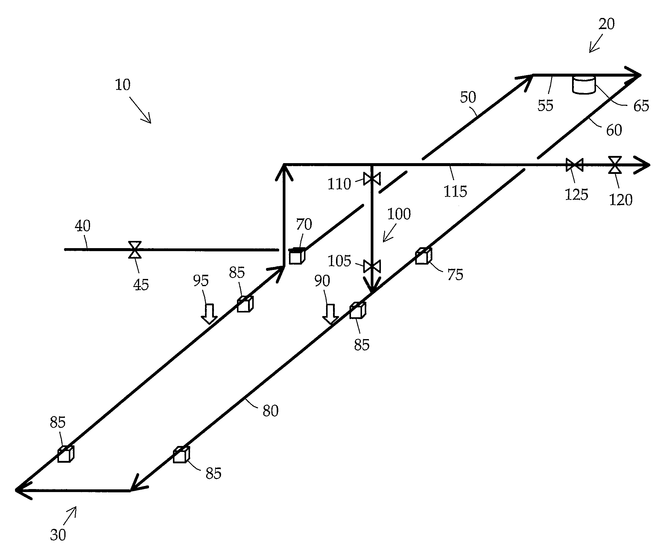
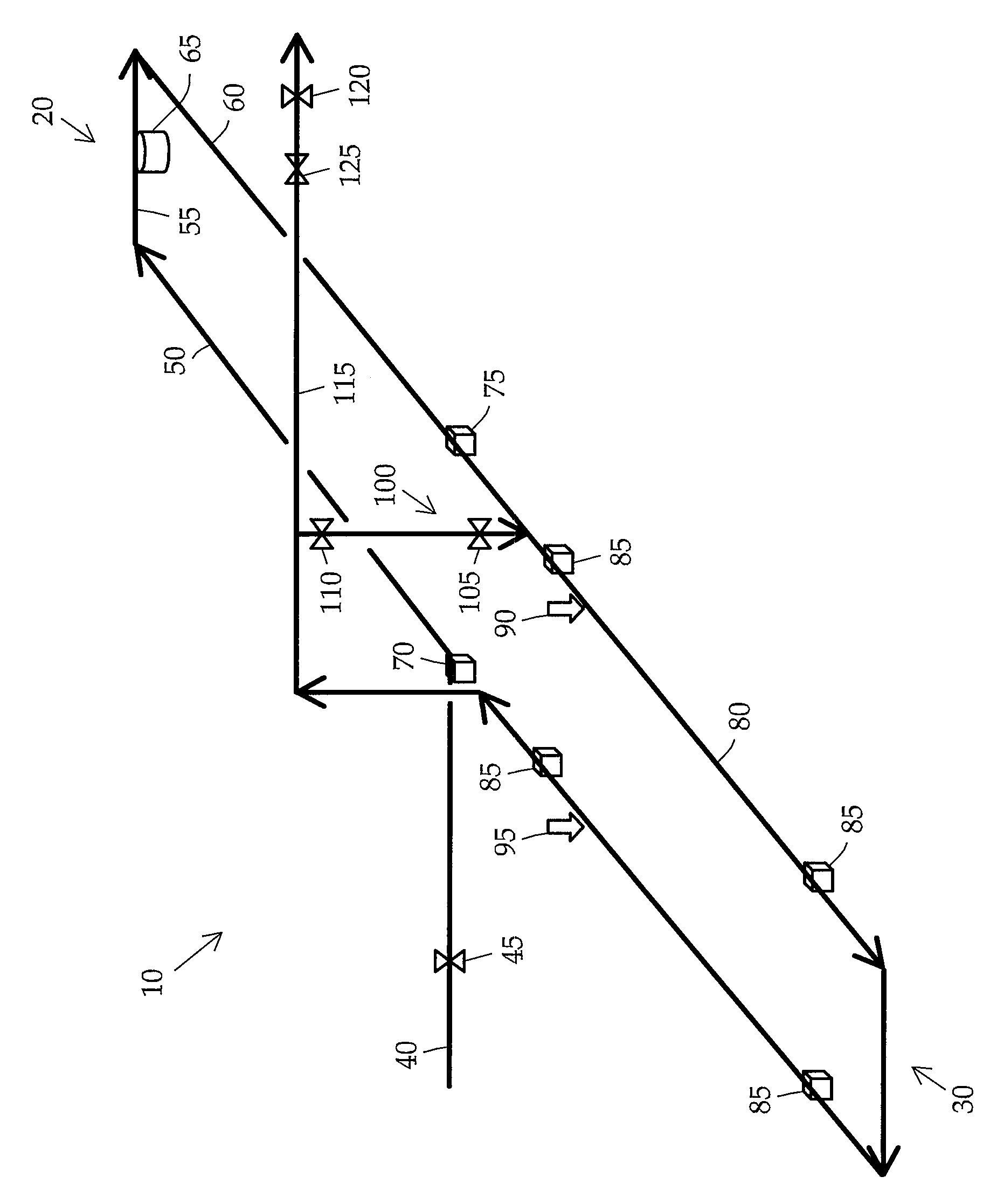
[0010]Turning now to the drawing, an embodiment of the system of the present invention is illustrated. The system combines a density determination end and a volumetric flow rate determination end. The resulting density and volumetric flow rate measurements can be used to calculate the mass flow rate of a single- or multi-phase fluid stream. The system is useful in onshore and offshore applications and in both high and low pressure environments. As an example, the system may be used in deep subsea oil and gas producing locations to accurately determine the mass flow rate of fluid streams containing a mixture of water, natural gas, and hydrocarbon liquids.

[0011]The fluid stream to be measured is delivered to the system 10 through an inlet block valve 45 and pipe 40. The fluid stream from the inlet pipe 40 flows through the density determination end 20 of the system 10. Next, the fluid stream flows through the volumetric flow rate determination end 30 of the system 10. The fluid stream...


PUM


Abstract

A system and method for calculating the mass flow rate of a fluid stream are presented. The system includes an inlet pipe that receives the fluid stream, a density determination end, a volumetric flow rate determination end, and an outlet pipe. The density determination end may have pipe sections that are connected to each other, a weighing system to determine the apparent mass of the fluid stream, and inlet and outlet supports. The volumetric flow rate determination end of the system may be a piping system, displacer, displacer position sensors and a piping support system designed to determine the average flowing velocity of the fluid stream. The resulting density and volumetric flow rate measurements are multiplied to determine the mass flow rate of the fluid stream. The system and method are applicable to both single- and multi-phase streams and can be used in onshore and offshore applications.

Description

1. FIELD OF THE INVENTION[0001]The present invention relates to a system and method for determining the mass flow rate of a fluid stream flowing through a piping system. The system and method may be used for single- or multi-phase fluid streams in oil and gas producing locations, and is particularly applicable in deep subsea applications.2. BACKGROUND OF THE INVENTION[0002]Within the oil and gas industry, it is frequently necessary to determine the mass flow rate of a single- or multi-phase fluid stream flowing through a pipeline. For example, in a multi-phase produced stream containing water, natural gas, and liquid hydrocarbons, the mass flow rate may be used to determine the final volumes and the resulting value of each product stream.[0003]Separate gas and liquid flow meters are traditionally used to determine the total mass, energy and / or volumetric flow rate of multi-phase fluid streams. However, multiple meters, production separators and other related equipment are typically ...

Claims


Application Information

Patent Timeline
Patent Type & Authority Patents(United States)
IPC IPC(8): G01F1/86
CPCG01F1/86G01F1/90G01G17/04E21B47/10F17D3/18G01F1/74G01F25/0046G01G1/00G01F25/14
Inventor VAN, ORSDOL, FRED, G.
Owner VAN ORSDOL FRED G
Learn More