
Methods and systems for control of a surface modification process

a technology of surface modification and control method, applied in the direction of total factory control, programme control, sustainable manufacturing/processing, etc., can solve the problems of forming unwanted substances on the surface, the quality of the modified surface or specimen gradually deviating from the target value, and the deviation of the target value over time, so as to facilitate real-time optical control, increase manufacturing yield, and enhance productivity

Active Publication Date: 2014-12-23
ATANASOFF GEORGE
View PDF6 Cites 11 Cited by
  • Summary
  • Abstract
  • Description
  • Claims
  • Application Information

AI Technical Summary

Benefits of technology

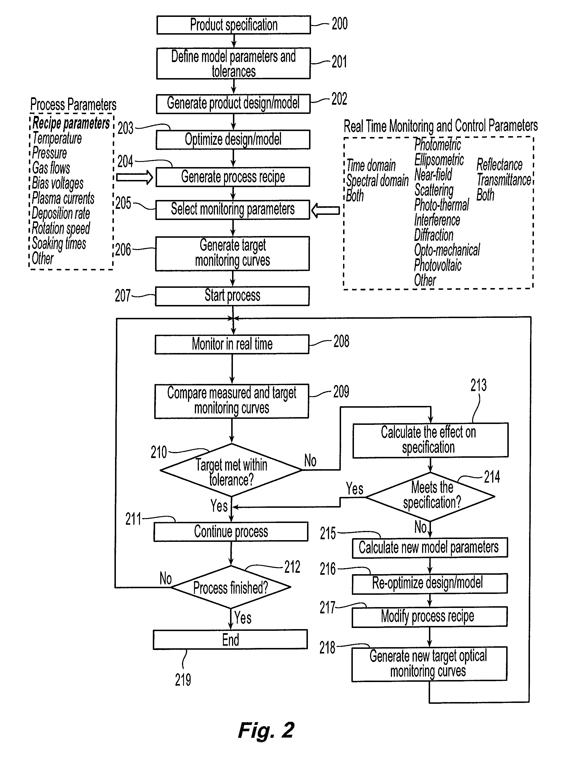
The present invention is a method for detecting and correcting errors in a thin film process, such as in the deposition of solar cells. The method uses an optical control system to pinpoint the errors quickly and accurately. The system monitors the process locally and can easily detect and locate errors in the thin film. The method can also compensate for errors by adjusting the thickness of layers in the process. The main advantage of the method is that it can be done without human involvement and can seamlessly correct errors in the design formula. The method can be used in various thin film processes, such as the deposition of amorphous silicon solar cells.

Problems solved by technology

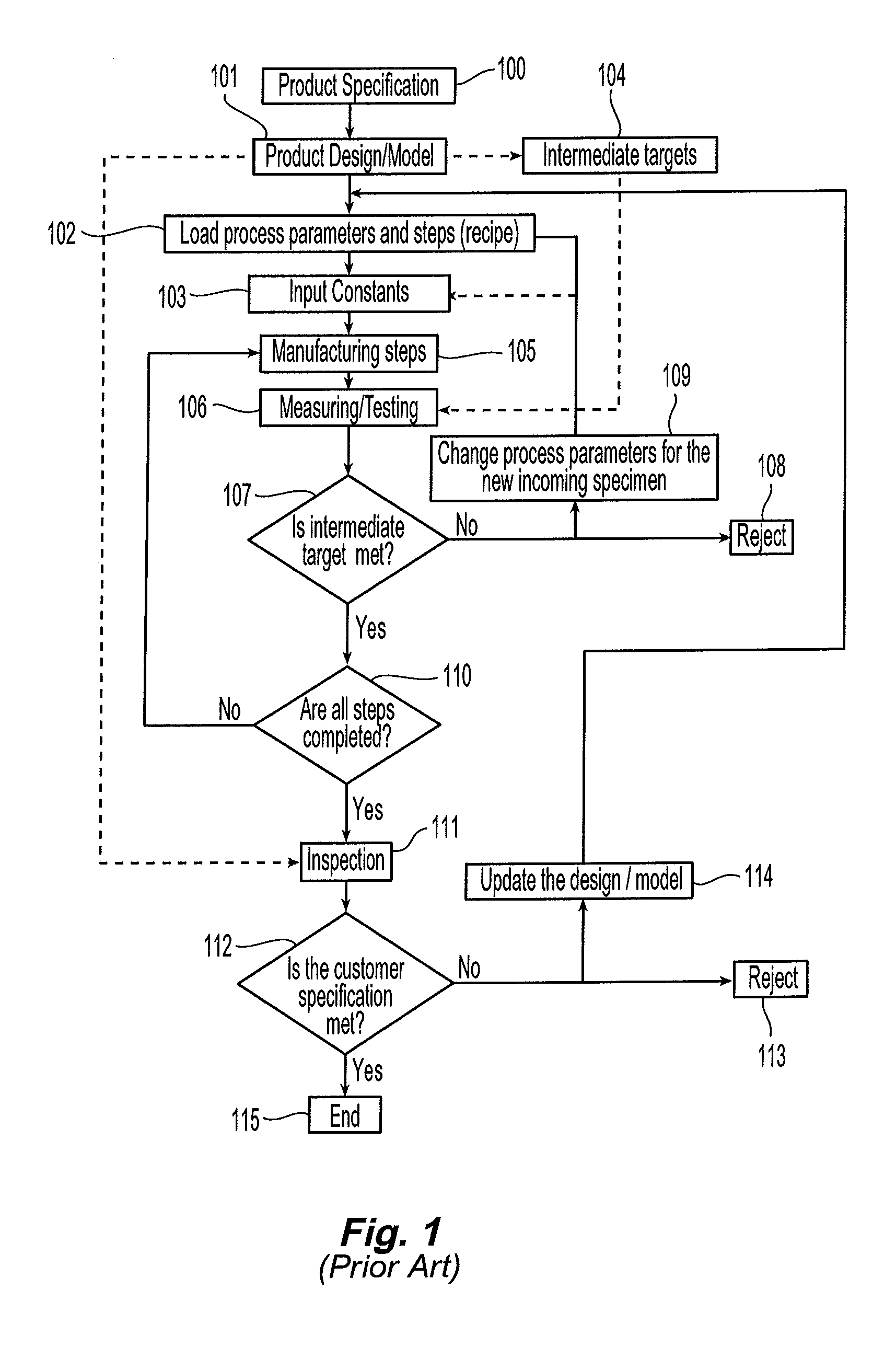
Most surface modification processes typically tend to “drift” over time, causing the modified surface or specimen to gradually deviate from the target values.
In the case of printing, a residual deposition of ink on the printing drums, variations in the viscosity of the printing inks, sublimation of thermoplastic resin or formation of toner particle layers on the rollers and drums in electro-photography, can cause gradual drift in the quality of the produced copies over time, and from location to location on the same sample.
In the case of surface grinding / polishing, a removal of material from the surface of the specimen and its subsequent incorporation into the polishing solution may gradually change the chemical properties of the polishing solution (such as its pH) causing formation of unwanted substances on the surface and gradual drift in the quality of the polished samples.
In the typical thin film deposition, one reason for the process to “drift” over time can be the overcoat of the processing chamber walls during the process, causing change in the thermal, optical or electrical properties inside the chamber.
In addition, there is a spatial distribution of the processing parameters inside the equipment due to geometrical or other reasons, causing non-uniformity in the plasma or gaseous phase distribution and, thus, non-uniformity of the film properties over the deposited specimen from location to location.
To further complicate the situation, this spatial parameter distribution inside the processing chamber can also drift over time.
A lattice mismatch small as a fraction of a percent can significantly affect the career mobility and decrease the current produced by the solar cell.
Even a very small change in any of the process parameters can cause a sufficient lattice mismatch and, thus, reduce the efficiency of the final product, making it to miss its product specification.
One result of this fact is that there is unavoidable percentage of rejects or final products, which are not able to meet the intended product design.
As for the flawed sample, it is usually considered a reject or a product with inferior quality.
This results in wasted materials, energy and labor and inflates the final product cost.

Method used


Image

  • Methods and systems for control of a surface modification process
  • Methods and systems for control of a surface modification process
  • Methods and systems for control of a surface modification process

Examples


Embodiment Construction

[0116]The various aspects of the preferred embodiments are now described with reference to the annexed drawings, wherein the numerals refer to like or corresponding elements throughout. It should be understood, however, that the drawings and detailed description relating thereto are not intended to limit the claimed subject matter to the particular form disclosed. Rather, the intention is to cover all modifications, equivalents and alternatives falling within the spirit and scope of the claimed subject matter.

[0117]As used herein, the term “product specification” is intended to include the description of the necessary attributes a finished product must attain in order for the product to be used for its intended purposes.

[0118]The term “product design” refers to a specific product formula or product structure the manufacturing process is required to follow in order to attain the necessary specifications at intermittent and final step of the deposition process. An example of a product...


PUM


Abstract

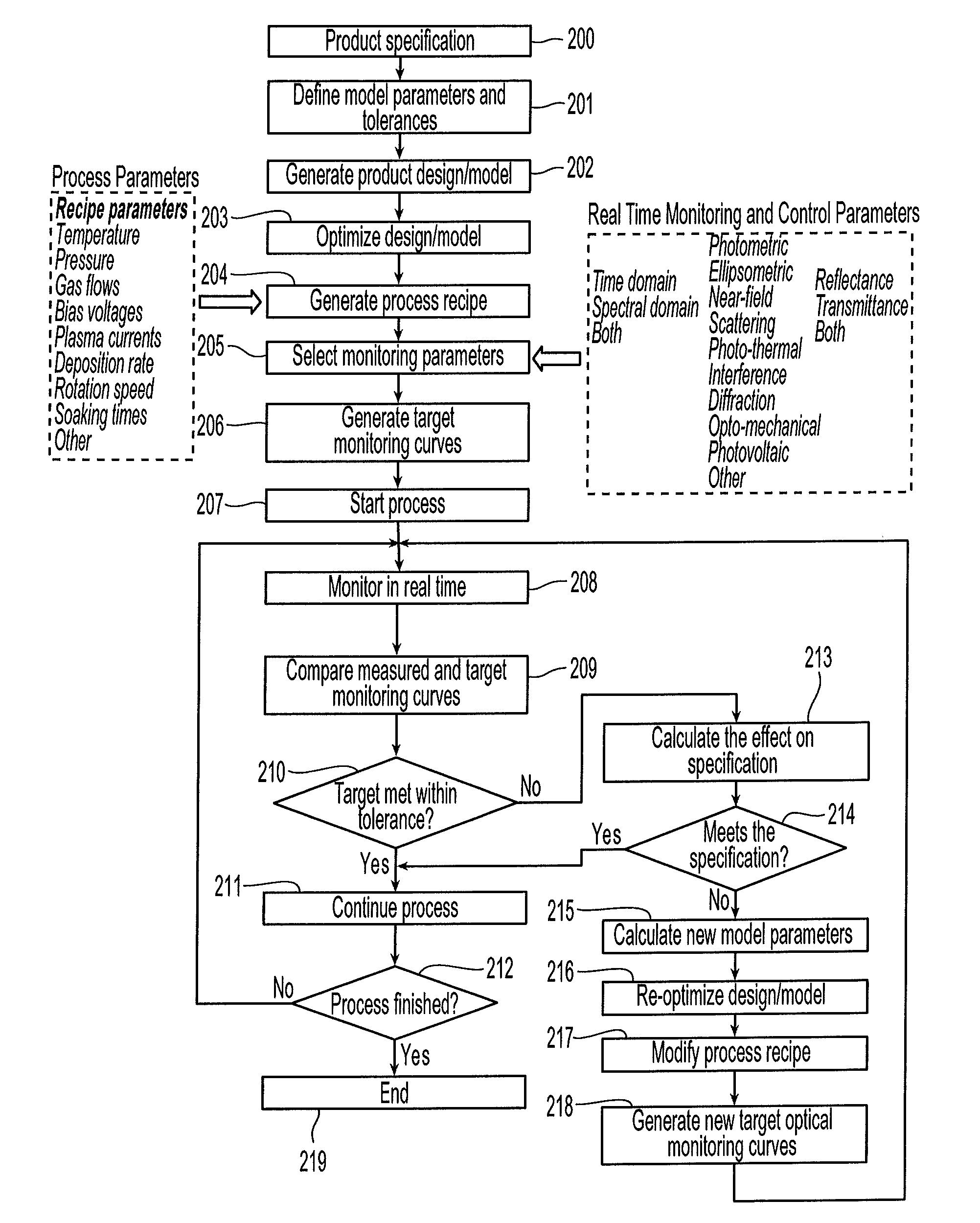
A method and system for modifying a substrate, such a thin film, solar panel or the like detects error and / or variance and, if needed, re-optimizes the product design and / or process parameters on the fly, so that product can meet the product specification. This allows for methods and systems of process control that can adaptively change the product design in real time.

Description

CROSS REFERENCE TO RELATED PROVISIONAL APPLICATIONS[0001]This application claims the benefit of U.S. Provisional Patent Application No. 61 / 146,143, filed Jan. 21, 2009, the entirety of which is incorporated herein.FIELD OF THE INVENTION[0002]The present innovation generally relates to control of surface modification processes, and more particularly relates to methods and systems that can be used to facilitate error detection and real time correction of a specimen undergoing a surface modification process.BACKGROUND OF THE INVENTION[0003]Many surface modification processes involve addition or subtraction of a layer or material on or from a specimen based on certain design, formula, recipe or physical pattern. Surface modification is used for a variety of purposes, for example, surface modification can be used to achieve desired optical, mechanical, electrical, photovoltaic or any other physical feature that influences performance. Surface properties such as roughness, relief, chemica...

Claims


Application Information

Patent Timeline
Patent Type & Authority Patents(United States)
IPC IPC(8): H01L31/032G05B13/04G06F19/00H01L31/20H01L31/18G05B19/4097G01B11/06
CPCG05B2219/35028H01L31/0322H01L31/20G05B19/4097H01L31/18Y02E10/541H01L31/206G01B11/0625G05B13/048G01B11/0683G05B2219/35081A61P31/04Y02P70/50Y02P90/02
Inventor ATANASOFF, GEORGE
Owner ATANASOFF GEORGE
Learn More