Surface flow finishing machine

a technology of surface flow and finishing machine, which is applied in the direction of plane surface grinding machine, metal-working apparatus, manufacturing tools, etc., can solve the problems of difficulty in loading and unloading, large capacity of the machine, and large difficulty in executing barrel by barrel

Active Publication Date: 2014-12-30
REDAELLI PAOLO
View PDF11 Cites 5 Cited by
  • Summary
  • Abstract
  • Description
  • Claims
  • Application Information

AI Technical Summary

Benefits of technology

[0024]An object of the present invention is to overcome the aforementioned drawback, by providing a surface finishing machine which allows combining versatility of use, execution rapidity with costs and low dimensions.
[0027]The invention has numerous advantages, for example including:a) Cost of the machine—the machine would have a slightly varied cost with respect to a machine of the prior art, solely the strictly necessary to obtain channels, or separate sections, within the vat;b) Space—the machine, for performing the task that in the prior art should be performed by two or three vats, maintains almost the same dimensions of a machine for a single step;
[0028]c) Versatility—the machine, due to the particular design of the multichannel vat, may mount a type of vat today and another one the following day, due to a gravity replacement, with coupling geometry. It is sufficient to arrange an overhead crane for lifting the vat from the seat thereof and, subsequently, fixing another one with different channels and / or with media loads of different formulation and / or composition;d) Execution speed—the times of displacement of a spindle from one channel to the next one are much quicker in seconds than the passage from one large vat and another large vat, with the consequence that such operation, deemed hundreds of times per day, would lead to quite considerable total difference times;e) Advanced technique—the peripheral speed of the most external channels is greater with respect to that of the intermediate channel and, also, with respect to the innermost one. This would allow an ideal distribution of the channels, where the outermost one could be preferably dedicated to the roughing action, the intermediate one to the polishing action and the innermost one to the fine polishing. Arranging media having an equivalent removal action but with large, medium and fine grain-size for large, medium and small articles, would allow meeting the expectations even in this case.f) Multitasking operations—the daily productivity needs impose the provision of batches of large, intermediate and small articles and, in the case of the rotary multichannel vat there are no difficulties to simultaneously provide, though using different channels, processes with three (or more) spindles simultaneously;g) Economy in the process costs—in the prior art it is necessary to displace three vats with, for example, 250 kg of load each. In order to develop such peripheral speed and such finishing, in the multichannel vats, it may be sufficient to limit the load up to ⅓, at times even more, with ensuing reduction of the media purchase, use and disposal costs.

Problems solved by technology

Even today many finishings obtained using satellite tumblers cannot be equalled, in the quality / cost ratio of the finishing process, with other known systems.
However a first drawback of this technique lies in the capacity of the machines, which can have extremely large dimensions.
A second drawback lies in the difficulty of loading and unloading, barrel by barrel.
A third considerable drawback lies in the difficulty of forming multi-step cycles, for example with intermediate rinsing operations, given that each would require a manual intervention opening the barrels one by one, and so on and so forth, this being another reason why they are more common in Asia, for example, than in Europe.
A drawback regarding the use of this type of technique regards the poor productivity; regardless of the speed and efficiency of the processes actually there can be loaded two pieces per cycle, by hand.
The use limit thereof is the cost of the spare discs, which are extremely high in some cases.
Each of these machines represent the state of the art and the frequency of application based on vibrating vats is very limited, if not entirely unused.
This system—also referred to as stream finishing—is quite complex from a mechanical point of view and it is based on an indexed head which supports rotary spindles.
a) Cost of the machine—the machine would have a slightly varied cost with respect to a machine of the prior art, solely the strictly necessary to obtain channels, or separate sections, within the vat;
b) Space—the machine, for performing the task that in the prior art should be performed by two or three vats, maintains almost the same dimensions of a machine for a single step;
c) Versatility—the machine, due to the particular design of the multichannel vat, may mount a type of vat today and another one the following day, due to a gravity replacement, with coupling geometry. It is sufficient to arrange an overhead crane for lifting the vat from the seat thereof and, subsequently, fixing another one with different channels and / or with media loads of different formulation and / or composition;
d) Execution speed—the times of displacement of a spindle from one channel to the next one are much quicker in seconds than the passage from one large vat and another large vat, with the consequence that such operation, deemed hundreds of times per day, would lead to quite considerable total difference times;
e) Advanced technique—the peripheral speed of the most external channels is greater with respect to that of the intermediate channel and, also, with respect to the innermost one. This would allow an ideal distribution of the channels, where the outermost one could be preferably dedicated to the roughing action, the intermediate one to the polishing action and the innermost one to the fine polishing. Arranging media having an equivalent removal action but with large, medium and fine grain-size for large, medium and small articles, would allow meeting the expectations even in this case.
f) Multitasking operations—the daily productivity needs impose the provision of batches of large, intermediate and small articles and, in the case of the rotary multichannel vat there are no difficulties to simultaneously provide, though using different channels, processes with three (or more) spindles simultaneously;
g) Economy in the process costs—in the prior art it is necessary to displace three vats with, for example, 250 kg of load each.

Method used


Image

  • Surface flow finishing machine
  • Surface flow finishing machine
  • Surface flow finishing machine

Examples


Embodiment Construction

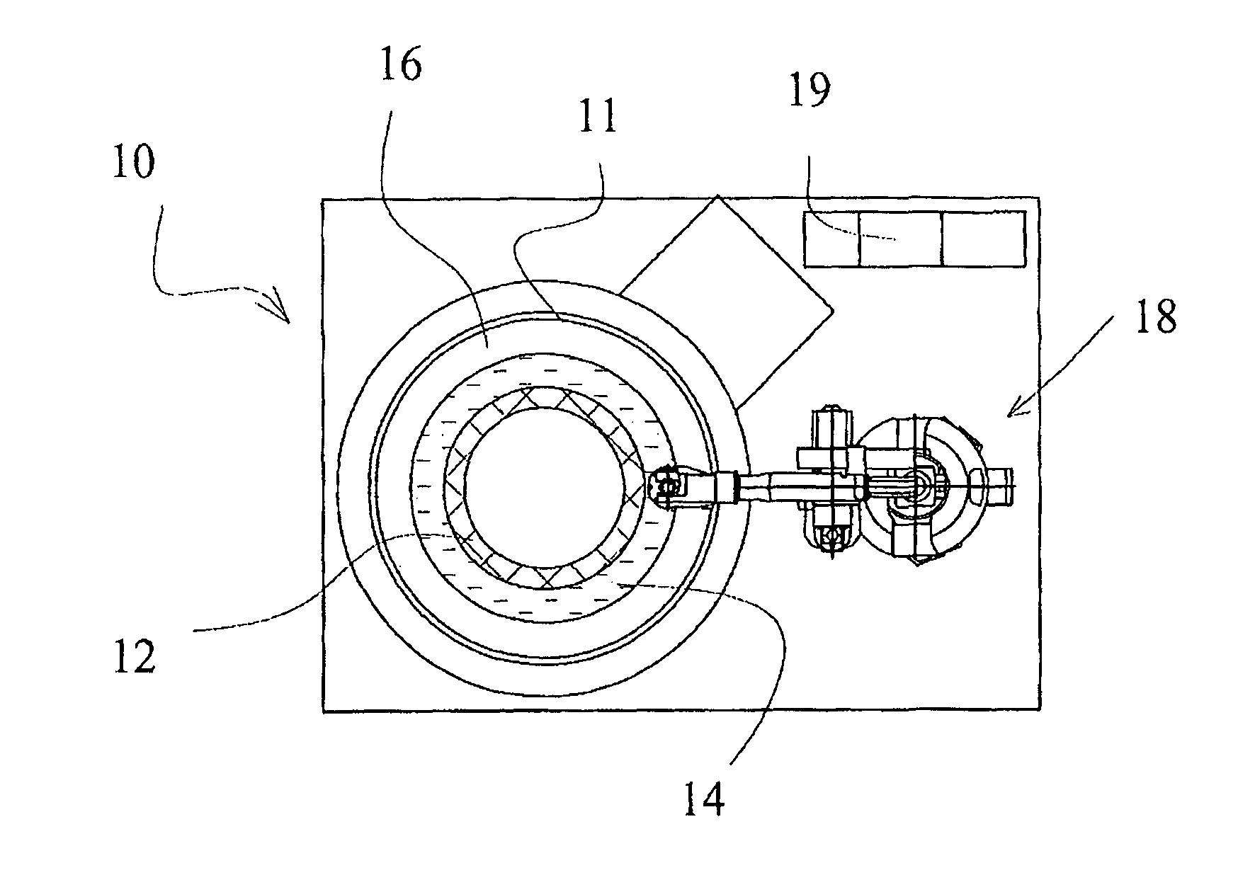
[0038]In particular, FIG. 1 shows a surface flow finishing machine according to the present invention, generally indicated with reference number 10. It comprises a rotary vat 11 for containing finishing media and a unit for moving pieces comprising at least one mechanical arm for moving the pieces being machined, which in the specific case is constituted by an anthropomorphic robot 18 adapted to pick pieces, whose surfaces should be machined by a bench 19, and rotate them within the rotary vat 11.

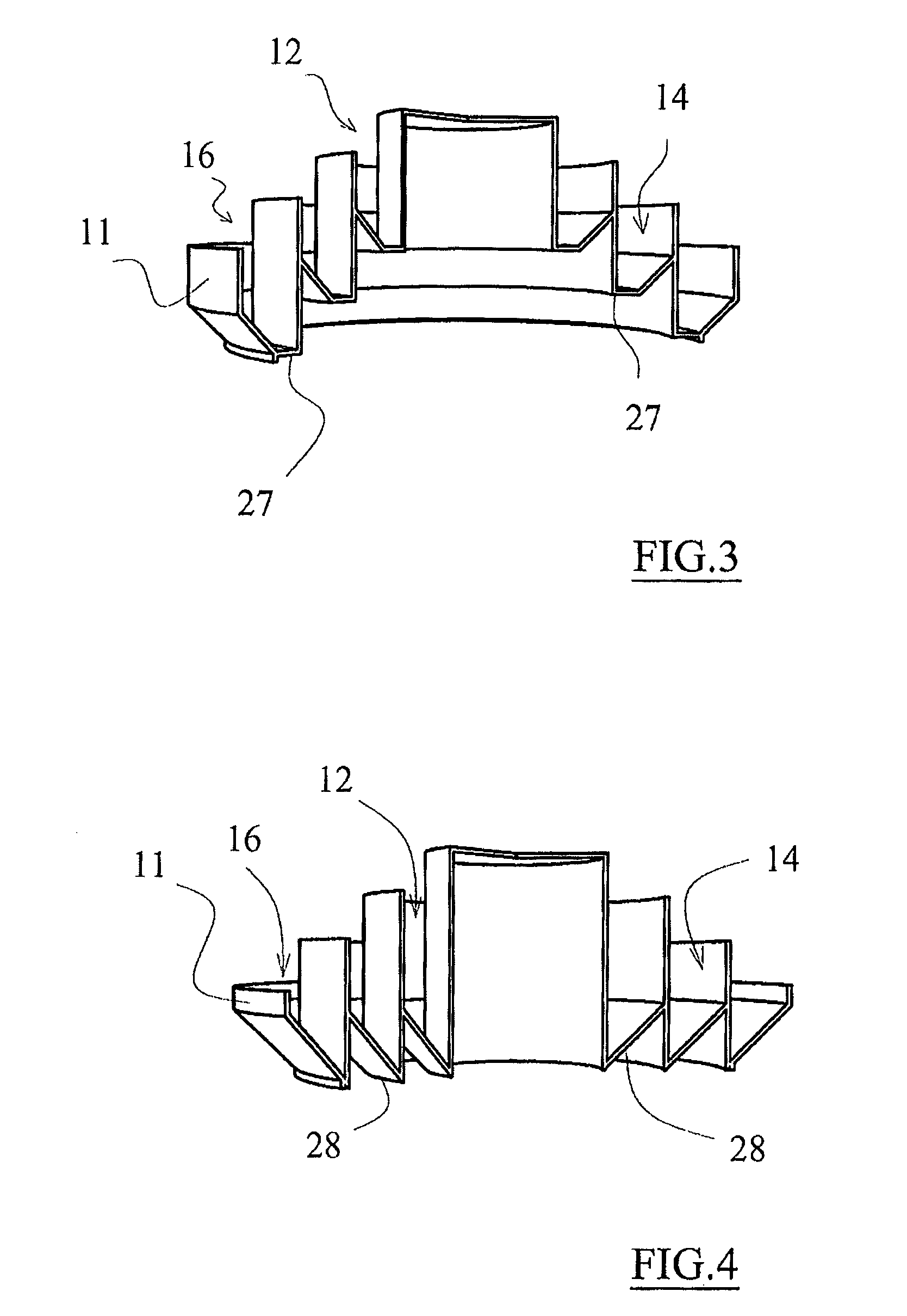
[0039]In particular, the rotary vat comprises three separate sections 12,14,16 formed by concentric circular crowns.

[0040]Preferably each of the separate sections 12,14,16 of the rotary vat 11 is adapted to receive a different finishing media.

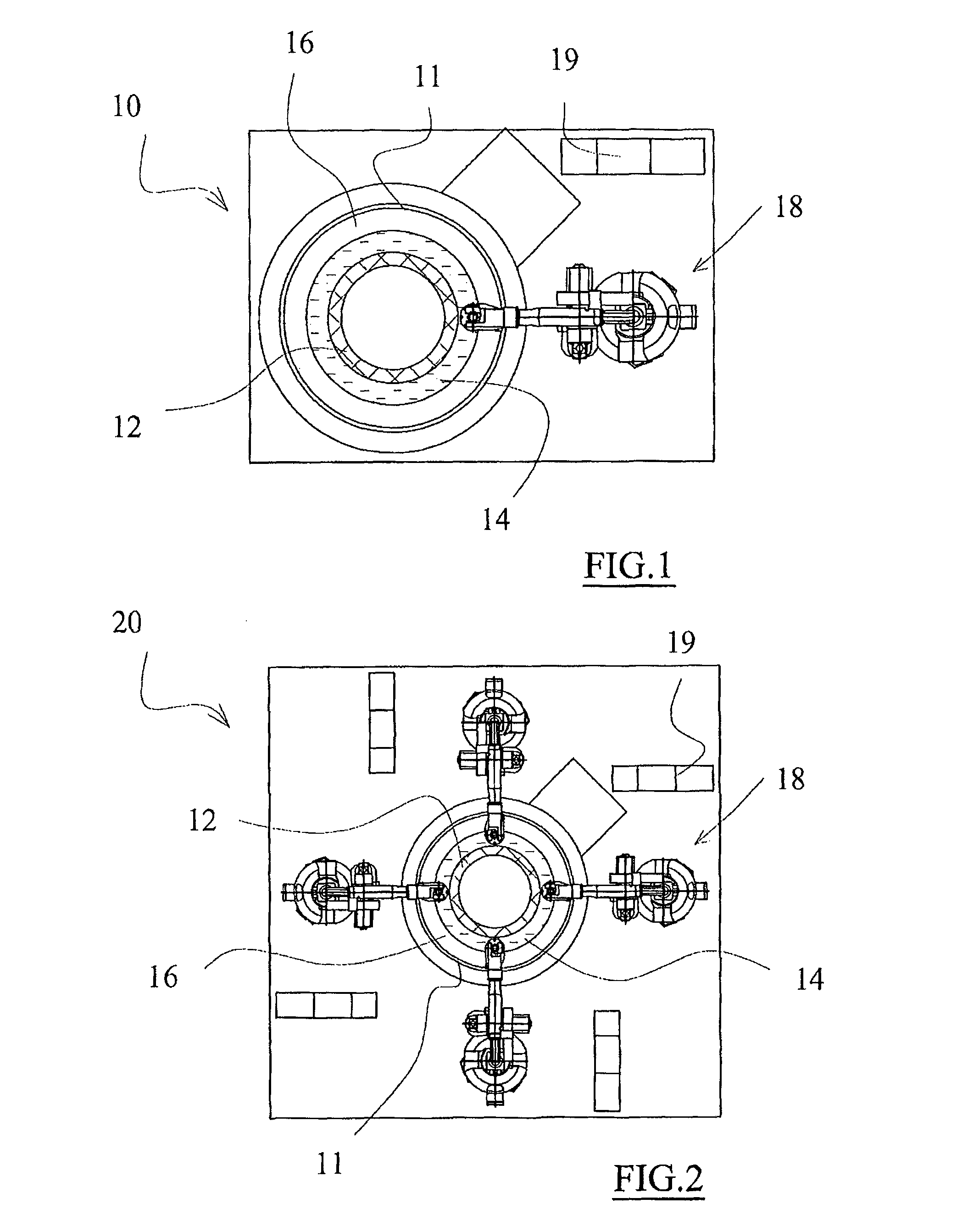
[0041]FIG. 2 shows—in top view—a second embodiment of the invention which differs from the embodiment of the figure due to the fact that it provides four anthropomorphic robots 18, each adapted to operate at a section of the rotary vat 11.

[0042]Each of...


PUM


Abstract

A machine for the flow finishing of mechanical pieces is described. The machine has a rotary vat for containing finishing media and a unit for moving pieces having at least one mechanical arm for moving the pieces being machined, said mechanical arm being associated to means for rotating the pieces within the rotary vat, the rotary vat has at least two separate sections formed by concentric circular crowns.

Description

CROSS REFERENCE TO RELATED APPLICATIONS[0001]The present application is the US national stage of International Patent Application PCT / IB2012 / 002467 filed on Nov. 21, 2012 which, in turn, claims priority to Italian Patent Application MI2011A002227 filed on Dec. 6, 2011.TECHNICAL FIELD[0002]The present invention refers to a surface flow finishing machine.BACKGROUND ART[0003]The history of metal (and non-metal) surface mass finishing is based on various modes regarding the method through which the mass constituted by the media and the pieces is moved.[0004]The first known mode in modern times (after the second world war) is that of the rotary tumbler, a cylindrical vat subjected to a rotary movement, within which the moving mass rolls, developing a typical “wave” movement on whose descending ramp there develops an interesting slide of the pieces, with extremely valid finishing levels, revealing the drawback of not being very fast.[0005]This method is common up to date, for example, in ...

Claims


Application Information

Patent Timeline
Patent Type & Authority Patents(United States)
IPC IPC(8): B24B31/00B24B31/02B24B31/023
CPCB24B31/0224B24B31/003B24B31/0212
Inventor REDAELLI, PAOLO
Owner REDAELLI PAOLO
Why Eureka
Try Eureka