Lightning protection sheet with patterned conductor

a protection sheet and conductor technology, applied in the installation of lighting conductors, aircraft static dischargers, relays, etc., can solve the problems of damage caused, measureable damage to modern light weight structures, and less effective protection of light weight structures from lightning, and achieve high electrical conductivity

Active Publication Date: 2014-12-30
3M INNOVATIVE PROPERTIES CO
View PDF71 Cites 23 Cited by
  • Summary
  • Abstract
  • Description
  • Claims
  • Application Information

AI Technical Summary

Benefits of technology

[0008]This disclosure generally concerns a lightning protection “sheet” comprising various “layers” and / or “films,” the lightning protection sheet providing protection to a “structure,” typically a surface of an aircraft or spacecraft.

Problems solved by technology

These lighter weight structures offer less effective protection against lightning than the traditional aluminum structures.
Much of the damage caused by a lightning strike is the result from extreme levels of heat at the strike location caused by the elevated temperature within the lightning arc and ohmic heating of the materials.
Strikes frequently destroy the protection mechanism at the attachment sites and cause measureable damage to modern light weight structures.
This necessitates costly structural repair and related service interruption.

Method used


Image

  • Lightning protection sheet with patterned conductor
  • Lightning protection sheet with patterned conductor
  • Lightning protection sheet with patterned conductor

Examples


examples

[0042]Unless otherwise noted, all reagents were obtained or are available from Aldrich Chemical Co., Milwaukee, Wis., or may be synthesized by known methods.

examples 1c-5c (comparative)

and 6-9

General Tooling and Bagging of a Composite Part

[0043]Composite specimens with a curable epoxy adhesive resin were prepared for curing in the following manner. A flat tool was fabricated by trimming to 2 ft×2 ft (0.61 m×0.61 m) a sheet of 12 gauge stainless steel alloy 304 with 2B finish. A 1 mil (25 micron) PTFE non-perforated parting film (available as HTF-621 from Northern Fiber Glass Sales, Inc.) was applied to the tool and affixed thereon with heat resistant tape applied at the edges and corners of the film. Each layer of material was applied to the tool in the order and arrangement described in the example text. Each layer was applied first to the tool, then one upon the other without liners by hand and each layer was consolidated with the previous layer(s) by passing a 1.5 inch (3.8 cm) diameter wooden roller over the upper-most layer while applying hand pressure to the roller. After every forth ply, the part and tool were covered with a layer of perforated parting film...

example 1c (comparative)

Carbon Fiber Reinforced Plastic Composite Structure with Polyurethane-Impregnated Expanded Aluminum Foil Applied After Cure

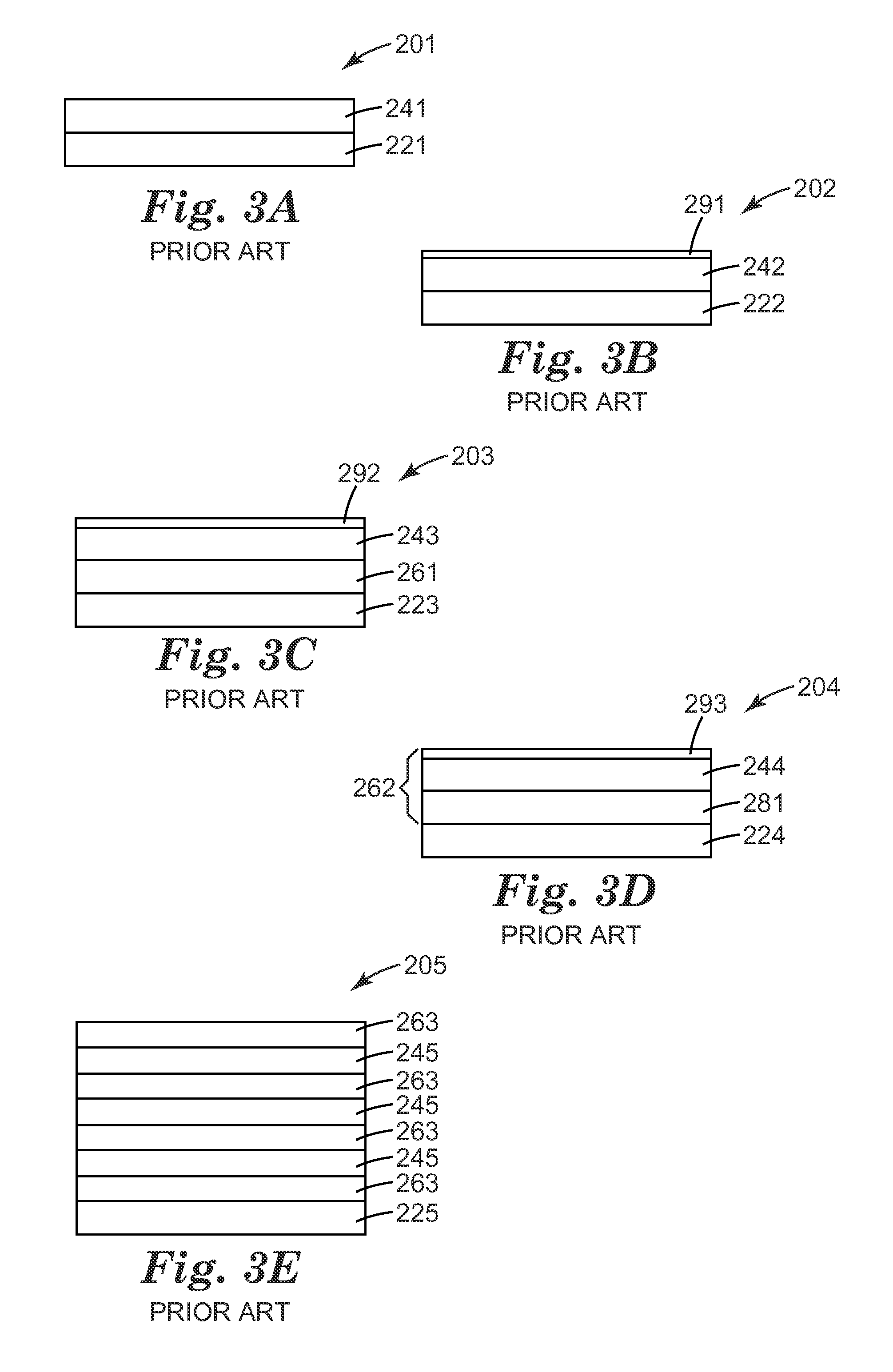
[0045]With reference to FIG. 3A, an epoxy resin impregnated carbon fiber, polyurethane resin and an expanded aluminum foil were provided and used to prepare comparative composite specimen (201). A cured carbon fiber reinforced plastic panel (221) was provided as follows. The following materials were assembled and prepared as described in “General Tooling and Bagging of a Composite Part” above. Applied to the tool were 13 plies epoxy resin impregnated unidirectional graphite fibers available as P2353U 19 152 from Toray. The curable resins in this assembly were cured as described in “Curing of a Composite Part” above. A layer comprising conductive mesh 241 was bonded to the surface as follows. A 4 mil thick expanded aluminum foil available as Exmet 4AL8-080 from Dexmet was placed flat on the part and saturated with polyurethane resin provided in the following mann...


PUM


Abstract

A lightning protection system is provided, typically for use on an outer surface of an aircraft, which includes the use of a lightning protection sheet that includes an electrically conductive film patterned into a plurality of hill features. The lightning protection sheet may additionally include an electrically non-conductive discriminator layer over the electrically conductive film.

Description

CROSS REFERENCE TO RELATED APPLICATION[0001]This application claims the benefit of U.S. Provisional Patent Application No. 61 / 170,352, filed Apr. 17, 2009, the disclosure of which is incorporated by reference herein in its entirety.FIELD OF THE DISCLOSURE[0002]This disclosure relates to a lightning protection sheet which includes an electrically conductive film patterned into a plurality of hill features, typically for use on an outer surface of an aircraft.BACKGROUND OF THE DISCLOSURE[0003]The lightning strike of an aircraft in flight is not a rare phenomenon. It is estimated that strikes on civilian transport planes amount to about one strike per plane per year. The current trend in aeronautical engineering is to use lighter weight materials, fewer mechanical systems and more electronic systems. Electronic systems are often more sensitive than mechanical systems to electromagnetic disturbances such as those generated by lightning. Recently, electrically non-conductive or partially...

Claims


Application Information

Patent Timeline
Patent Type & Authority Patents(United States)
IPC IPC(8): B64C1/12H05F3/00B64D45/02H02G13/00
CPCB64D45/02H02G13/00B64C1/12H02G13/80
Inventor HEBERT, LARRY, S.
Owner 3M INNOVATIVE PROPERTIES CO
Why Eureka
Try Eureka