Electronic component for surface mounting

a technology of electronic components and surface mounting, which is applied in the direction of transformer/react mounting/support/suspension, electrical apparatus construction details, ac-dc conversion, etc., can solve the problems of increasing the difficulty of reliable manufacture of such devices, problems such as moisture sensitivity as well as solder reflow, and the reliability of devices can be affected, so as to facilitate air circulation and simplify the construction of the body portion. , the effect of improving reliability

Active Publication Date: 2014-12-30
MURATA POWER SOLUTIONS MILTON KEYNES
View PDF19 Cites 5 Cited by
  • Summary
  • Abstract
  • Description
  • Claims
  • Application Information

AI Technical Summary

Benefits of technology

[0016]Mounting the circuit boards as the sides of the component allows the footprint of the device to be greatly reduced. Additionally, as the reverse side of the circuit board acts as the external housing of the device, the need for a separate housing is removed and problems with heat accumulation are avoided.
[0025]The intermediate section may include an internal cavity arranged to mount an electrical element, such as a transformer. In this way, the electrical component can be a power supply converter such as a DC-DC converter, or an isolator. In the case of the converter, the first and second body portion circuit boards can define the input and output feed circuits for the transformer, and the at least one conductive pin is provided in the top section and defines transformer wire wrap terminals to connect the transformer between the input and output feed circuits. The device provided in this way includes an extremely small footprint and a reliable construction.

Problems solved by technology

Changes in the materials which are considered acceptable for use in manufacture, mandated by the Restriction of Hazardous Substances (RoHS) provisions, for example, have made the reliable manufacture of such devices increasingly difficult.
When working on encapsulated devices, such as those discussed above, the increased working temperature is now sufficient to cause problems with moisture sensitivity as well as solder reflow, essentially melting solder that has already been applied internally to the module.
As a result, problems with the reliability of the device can occur.
However, because of minimum wall thickness and injection molding tolerances, the final device would necessarily be larger and more complex.
Furthermore, for DC-DC converter modules, the large number of terminations required for the components, typically nine transformer terminations and at least 4 pins for input and output, means that space is at a premium, and the size of the device is limited.

Method used


Image

  • Electronic component for surface mounting
  • Electronic component for surface mounting
  • Electronic component for surface mounting

Examples


Embodiment Construction

[0036]An example of a preferred embodiment of the present invention will now be described in more detail with reference to FIG. 2.

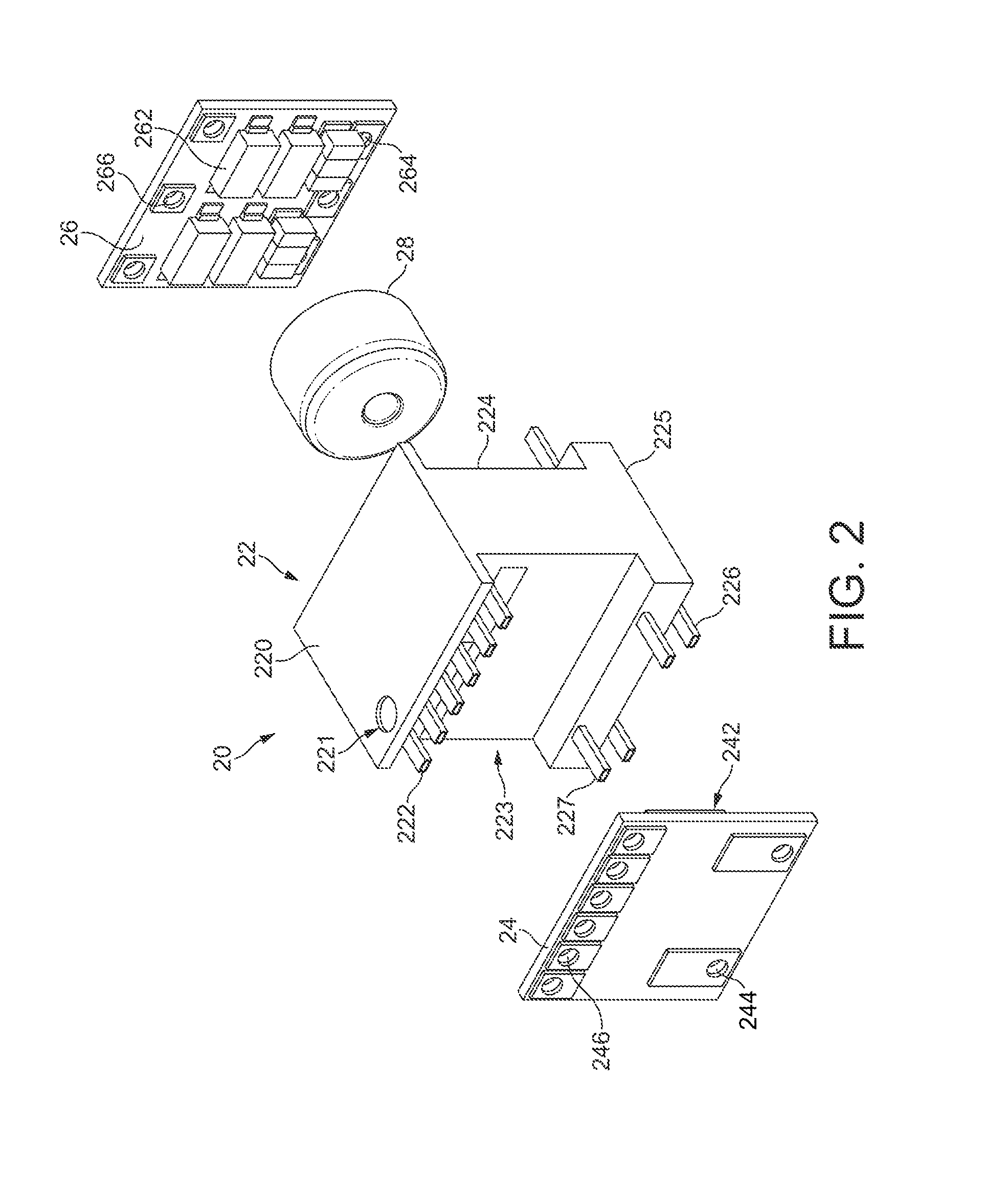
[0037]FIG. 2 shows, in an exploded isometric view, an electronic device for surface mounting applications according to an example of a preferred embodiment of the present invention. The device illustrated is a self oscillating push-pull DC to DC power converter. Preferred embodiments of the present invention are not however intended to be limited to such devices, and other example devices will be discussed later.

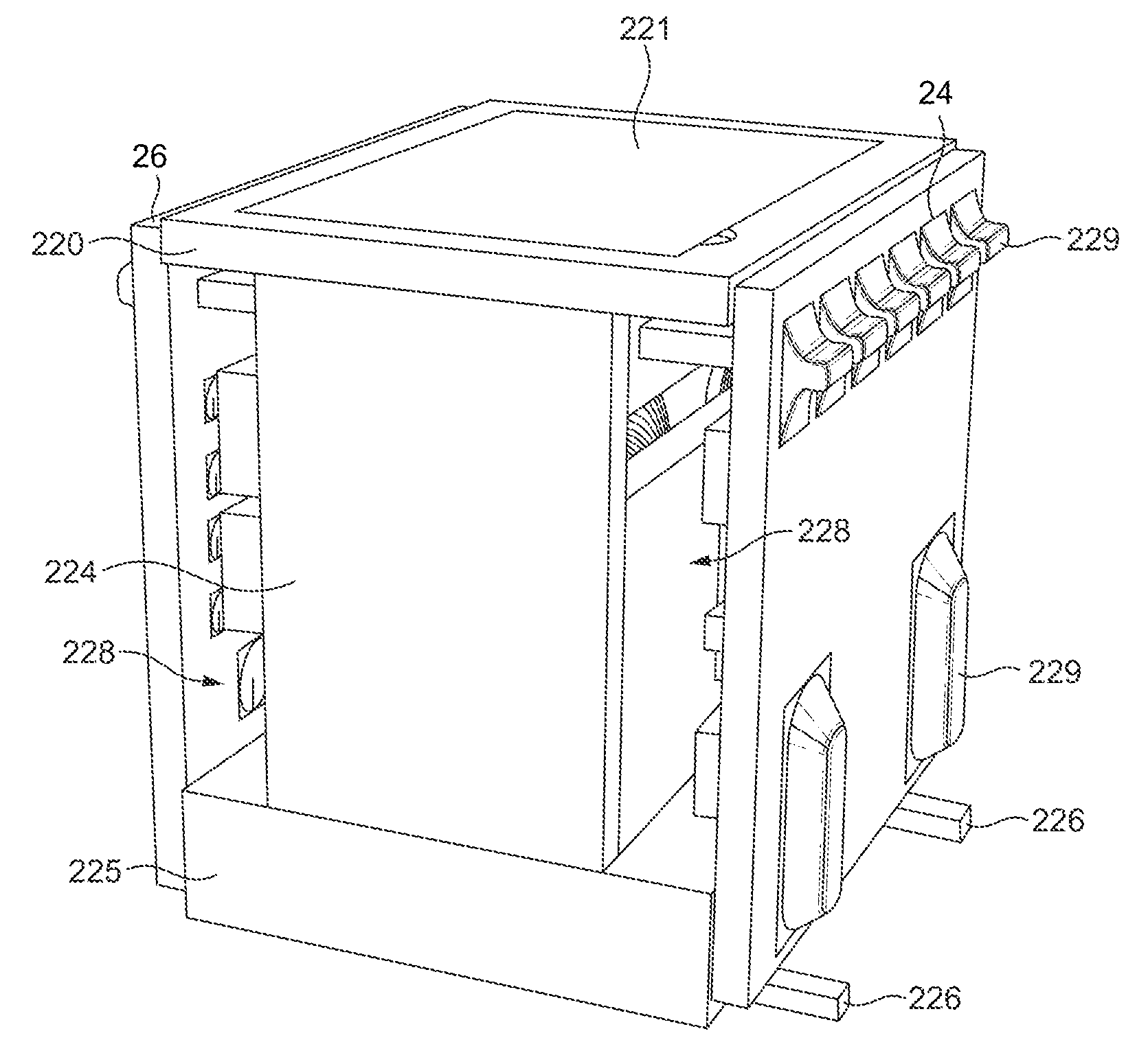
[0038]The DC-DC power converter 20 shown in FIG. 2 includes a central header or body portion 22, first and second circuit boards 24 and 26, and transformer coil 28. As shown in FIG. 3, to which reference should briefly now be made, the first and second circuit boards 24 and 26 attach to the body portion 22 to define two sides of the device 20, with the transformer coil 28 housed inside the body portion 22 and sandwiched inside the first and second...


PUM

PropertyMeasurementUnit
temperaturesaaaaaaaaaa
lengthaaaaaaaaaa
lengthaaaaaaaaaa

Abstract

An electrical component for surface mounting, such as a DC-DC power converter includes a body portion including one or more surface mounting pins to connect the body portion to a circuit board, and first and second circuit boards including respective circuit elements mounted thereon. The first and second circuit boards are mounted on the body portion, such that sides of the first and second circuit board on which the circuits are mounted face the interior of the device and the reverse sides of the first and second circuit boards define an exterior surface of the component. In this way, no separate housing for the component is required. The size of the electrical component can therefore be kept small, and protection provided to the circuit elements by the reverse side of the circuit board.

Description

BACKGROUND OF THE INVENTION[0001]1. Field of the Invention[0002]The present invention relates to an electronic component for surface mounting applications, and in particular to a power supply device including a DC-DC converter.[0003]2. Description of the Related Art[0004]A known power device module for surface mounting applications is illustrated in FIGS. 1a-1d. FIG. 1a is a top view of the device; FIGS. 1b and 1d are side views; and FIG. 1c is an isometric view.[0005]The module includes a generally rectangular transfer moulded housing 10 forming a closed device in which the converter electronics are contained. Terminal connections 11 from the internal electronics pass through the sides and form connecting feet 12 that can be attached to a base board (not shown). The module can be built using a transfer moulded lead frame, allowing the product to be developed with minimum tolerances while maintaining a small size and flat top and bottom sides for ease of handling.[0006]The power dev...

Claims


Application Information

Patent Timeline
Patent Type & Authority Patents(United States)
IPC IPC(8): H05K7/00H01F27/06H05K1/14H02M7/00
CPCH01F2027/065H05K1/145H02M7/003Y10T29/4913
Inventor PARISH, SCOTT
Owner MURATA POWER SOLUTIONS MILTON KEYNES
Why Eureka
Try Eureka