Contact terminal having a plunger pin

a contact terminal and plunger pin technology, applied in the direction of coupling contact members, coupling device connections, instruments, etc., can solve the problems of excessive heating of spring coils, undesirable to increase the diameter (width) of the contact terminal, and rapid increase of electrical resistance, etc., to achieve reliable flow, improve stability, and improve the effect of electrical resistan

Inactive Publication Date: 2015-01-06
SHIMANO MFG
View PDF24 Cites 18 Cited by
  • Summary
  • Abstract
  • Description
  • Claims
  • Application Information

AI Technical Summary

Benefits of technology

[0012]In the above-described invention, a second sac hole having a diameter smaller than a diameter of the insulation ball may be formed by cutting in a bottom portion of the non-penetrating hole of the main body case, and the second sac hole may receive a part of the coil spring at and near an end portion of the coil spring. According to this invention, even if the coil spring is compressed, the center axis of the coil spring does not largely change, so that a contact position between the insulation ball and the coil spring does not change. Accordingly, while a current does not flow in the coil spring, a current can be made to reliably flow from the plunger pin to the main body case. As a result, a relatively large current can be made to flow in the contact terminal.
[0014]In the above-described invention, the cut space may be a sac hole. According to this invention, the insulation ball is received in the sac hole so that a position of the insulation ball can be stabilized. Accordingly, while a current does not flow in the coil spring, a current can be made to reliably flow from the plunger pin to the main body case. As a result, a relatively large current can be made to flow in the contact terminal.
[0018]In the above-described invention, an inner surface of the groove portion may have a gutter-shape. According to this invention, a position of the insulation ball relative to the plunger pin is stabilized. Accordingly, while a current does not flow in the coil spring, a current can be made to reliably flow from the plunger pin to the main body case. As a result, a relatively large current can be made to flow in the contact terminal.
[0019]In the above-described invention, the gutter shape of the inner surface may have an imaginary radius smaller than a radius of the insulation ball. According to this invention, a position of the insulation ball relative to the plunger pin is more stabilized. Accordingly, while a current does not flow in the coil spring, a current can be made to reliably flow from the plunger pin to the main body case. As a result, a relatively large current can be made to flow in the contact terminal.

Problems solved by technology

As a result, electrical resistance rapidly increases, and the spring coil is thereby heated excessively to be burned out.
To make it possible to use a contact terminal so as to satisfy these demands of such various types of devices, it is not desirable to increase a diameter (width) of the contact terminal to increase the sectional area.

Method used


Image

  • Contact terminal having a plunger pin
  • Contact terminal having a plunger pin
  • Contact terminal having a plunger pin

Examples


embodiment 1

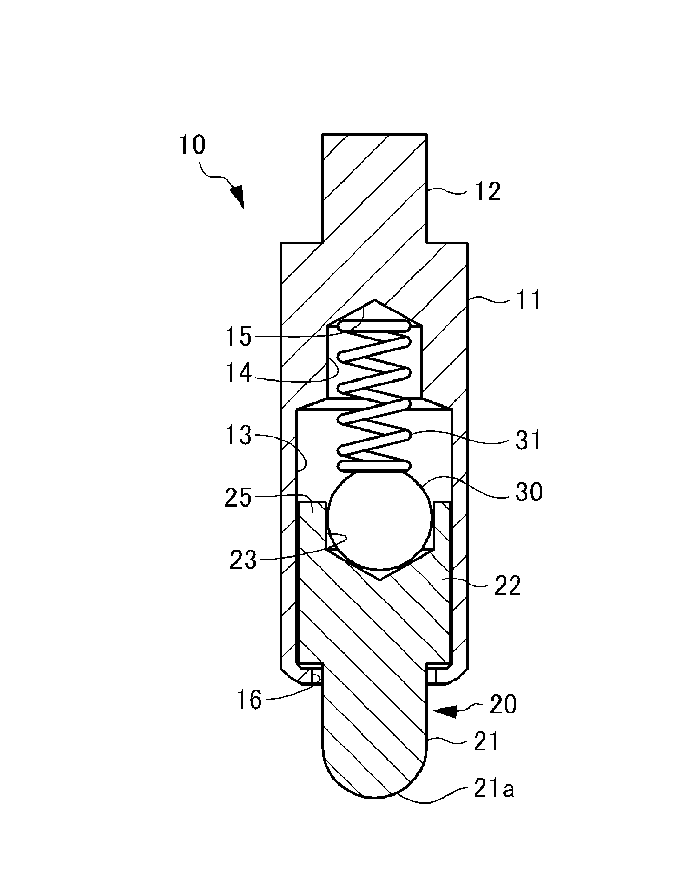
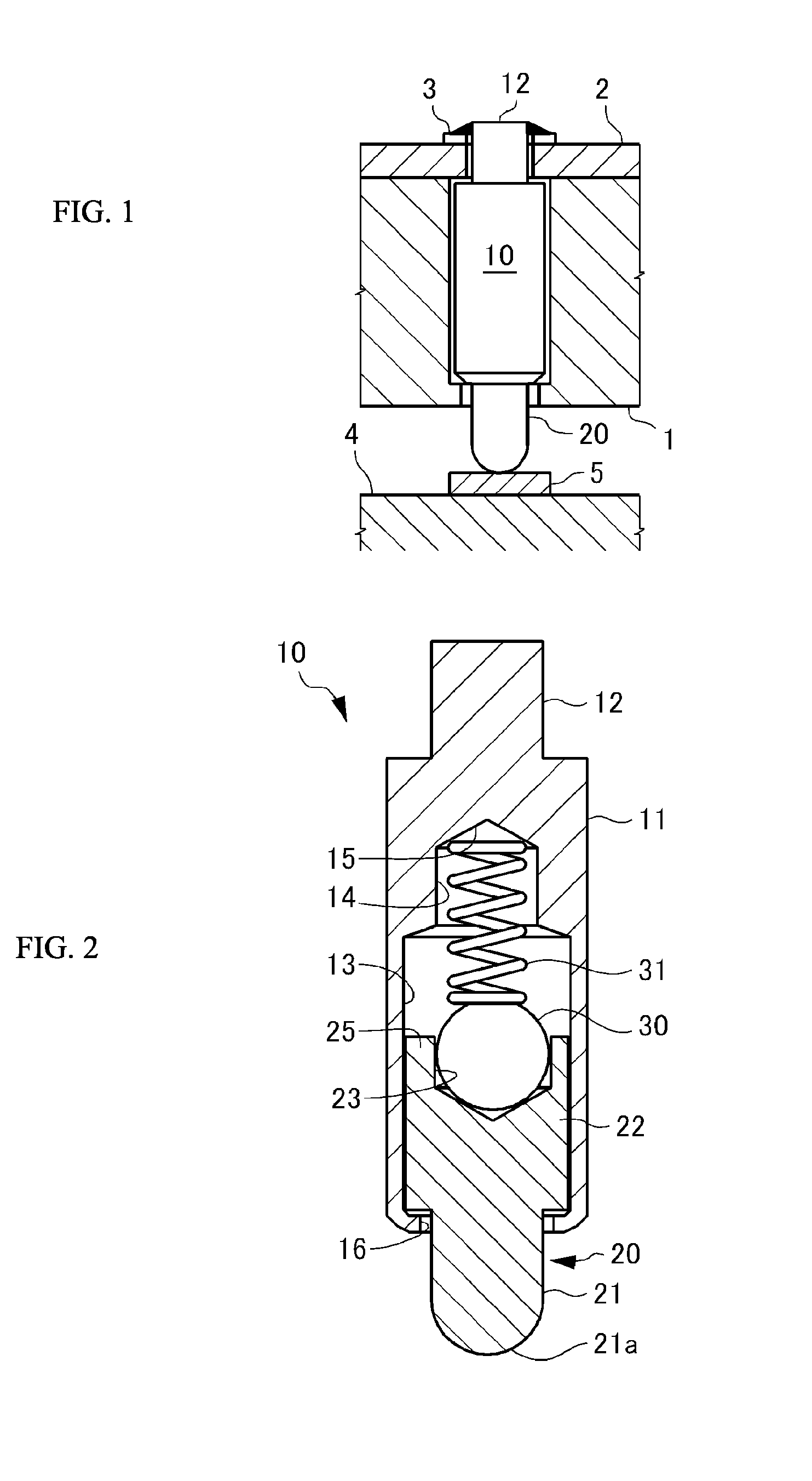
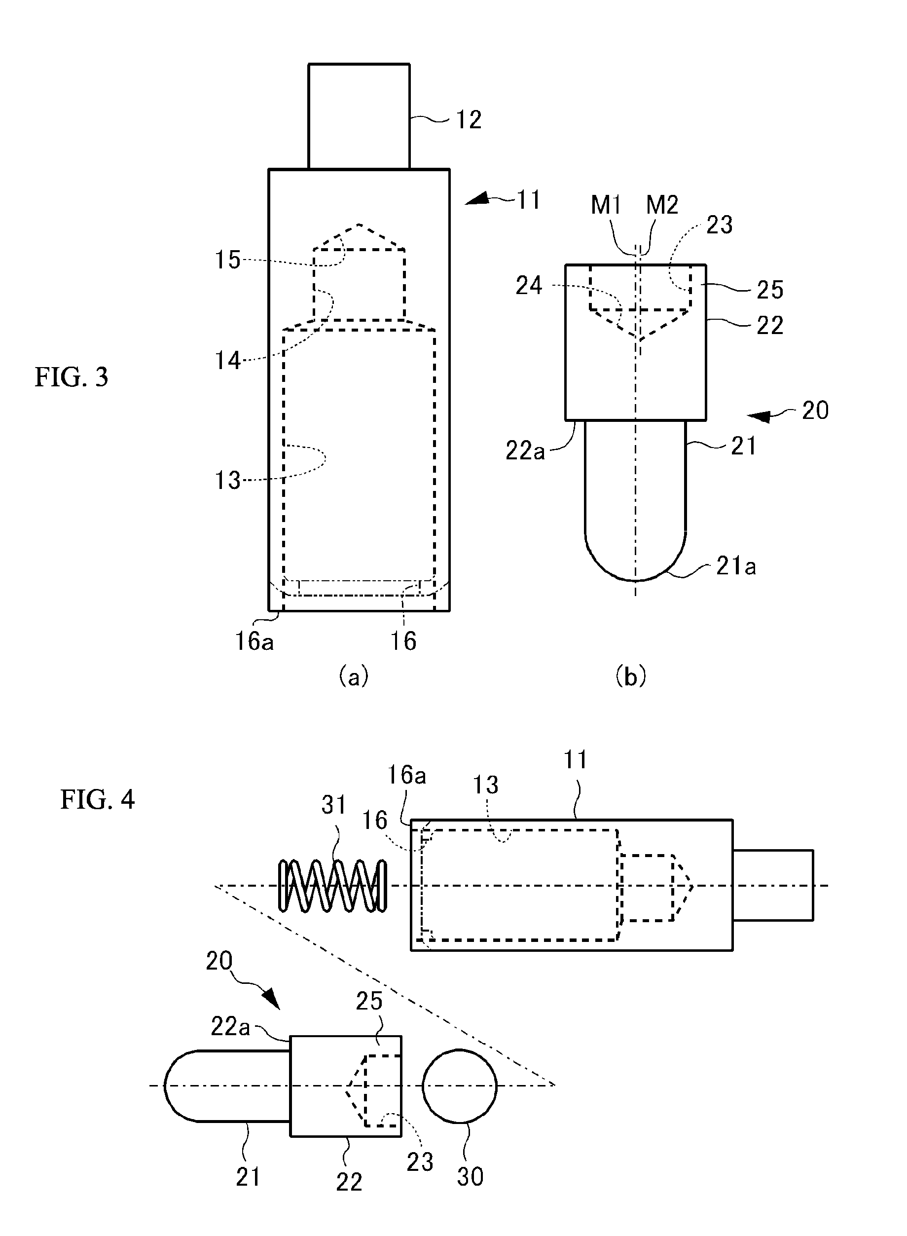
[0026]A contact terminal according to one embodiment of the present invention will be described in detail with reference to FIGS. 1 to 4.

[0027]As illustrated in FIG. 1, a contact terminal 10 is received by a socket 1 such that a pin part 12 and a plunger pin 20 of the contact terminal 10 protrude from both main surfaces of the socket 1, respectively. The socket 1 is a plate-shaped block body that is made of an insulation material such as resin and in which a penetration hole is formed. For example, the pin part 12 is inserted into a penetration hole of a printed circuit board 2 installed on one of the main surfaces of the socket 1 to be electrically connected to a circuit terminal 3 on the printed circuit board 2 by solder. A tip end part of the plunger pin 20 is contacted with a target part to which electrical connection is to be made. The target part is an electrode 5 arranged on an electrode block 4, for example. Thus, the contact terminal 10 is used for making connection to a po...

embodiment 2

[0041]With reference to FIGS. 5 and 6, a contact terminal according to another embodiment of the present invention will be described.

[0042]As illustrated in FIG. 5, in the contact terminal 10′, a shape of a plunger pin 40 is different from the shape in the contact terminal 10 according to the embodiment 1. Meanwhile, since other components, i.e., the main body case 11, the insulation ball 30 and the coil spring 31 of the contact terminal 10′ are the same as those of the contact terminal 10 according to the embodiment 1, description of these components will be omitted.

[0043]Referring to both of FIGS. 5 and 6, the plunger pin 40 received in the elongate hole 13 has a round-bar shape, and includes a step. The plunger pin 40 includes a small diameter portion and a large diameter portion. The plunger pin 40 includes a pin portion 41 as the small diameter portion, the large diameter portion 42 as a main body, and a step portion 42a between the pin portion 41 and the large diameter portion...


PUM


Abstract

A contact terminal having a main body case and a plunger pin received in an elongate hole formed in the main body case is provided. The plunger pin is a round bar provided with a step and includes a small diameter portion including the protrusion end portion and a large diameter portion that slides on a surface of the hole to freely move in a longitudinal direction thereof. A cut space is formed to extend from an end of the large diameter portion so as to leave at least a part of a side surface portion of the large diameter portion and the cut space receives an insulation ball including at least an insulation surface. A coil spring is arranged between the hole and the insulation ball to press the protrusion end portion of the plunger pin such that the protrusion end portion protrudes from the main body case.

Description

BACKGROUND OF INVENTION[0001]1. Field of Invention[0002]The present invention relates to a contact terminal used for the purpose of making electrical connection for connection to a power source, or inspection of a printed circuit board, an electronic component or the like. Particularly, the present invention relates to a contact terminal enabling a relatively large current to flow.[0003]2. Description of the Background Art[0004]A contact terminal used for connection to a power source, or inspection of a printed circuit board, an electronic component or the like is a component for obtaining electrical connection while making one end portion of the contact terminal contact with a terminal on a board. According to many types of contact terminals, a coil spring is inserted into an elongate hole provided in a metal-made main body case, a plunger pin is then inserted into the elongate hole, and only a front end portion of the plunger pin is maintained to protrude from the main body case. ...

Claims


Application Information

Patent Timeline
Patent Type & Authority Patents(United States)
IPC IPC(8): H01R13/24G01R1/067
CPCH01R13/2421G01R1/06722G01R31/2601H01R12/71H01R12/73
Inventor MORI, SHUHI
Owner SHIMANO MFG
Why Eureka
Try Eureka