Capacitor discharger for power conversion system

a technology of power conversion system and capacitor, applied in the direction of electric energy management, dc-ac conversion without reversal, transportation and packaging, etc., to achieve the effect of sufficient insulation distance and efficient heat dissipation

Active Publication Date: 2015-01-06
DENSO CORP
View PDF8 Cites 1 Cited by
  • Summary
  • Abstract
  • Description
  • Claims
  • Application Information

AI Technical Summary

Benefits of technology

[0009]In the above embodiment, a pair of series connections of resistive elements, each of which is a series connection of a plurality of resistive elements, are electrically connected in parallel between a pair of input terminals of the power conversion circuit. Therefore, for example, even in the presence of an open fault in a portion of the parallel connection of the pair of series connections of resistive elements, a discharge path for the capacitor can be ensured.
[0010]In addition, in the above embodiment, a discharge path for the capacitor is formed of the pair of series connections of resistive elements. This may lead to efficient dissipation of heat generated by a current flowing through each series connection of resistive elements and may ensure a sufficient insulation distance between a pair of terminals of each series connection of resistive elements.

Problems solved by technology

In the disclosed power conversion system, however, an abnormality, such as a disconnection (referred to as an open fault) or the like, in the discharge resistive element may prevent the capacitor from being discharged.

Method used


Image

  • Capacitor discharger for power conversion system
  • Capacitor discharger for power conversion system
  • Capacitor discharger for power conversion system

Examples


first embodiment

[0023]There will now be explained a power conversion system in accordance with a first embodiment of the present invention with reference to FIG. 1, to which a capacitor discharger of the present invention is applied. The power conversion system is electrically connected to a main rotating machine for a hybrid vehicle.

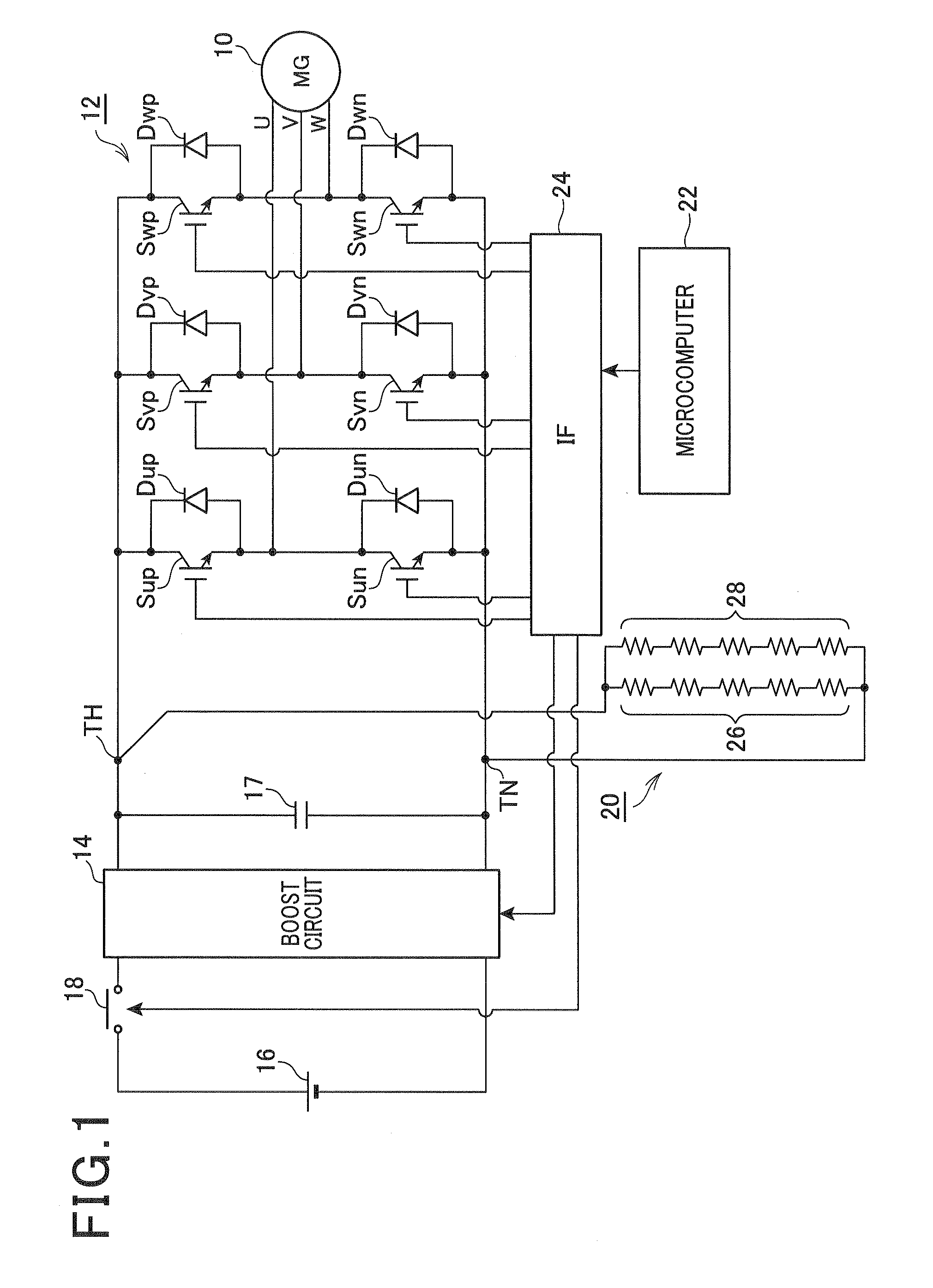
[0024]FIG. 1 schematically shows the power conversion system of the first embodiment.

[0025]As shown in FIG. 1, a motor-generator 10, as a prime mover for a vehicle, is mechanically connected to a drive wheel (not shown). The motor-generator 10 is electrically connected to a high-voltage battery 16 via an inverter 12 and via a boost circuit 14.

[0026]More specifically, the high-voltage battery 16 may be a secondary battery whose terminal voltage is equal to or greater than 100 V. The boost circuit 14 includes a series connection of a pair of switching elements (not shown), a capacitor 17 (referred to as a smoothing capacitor) electrically connected in parallel with the s...

second embodiment

[0043]There will now be explained a power conversion system in accordance with a second embodiment of the present invention. Only differences of the second embodiment from the first embodiment will be explained.

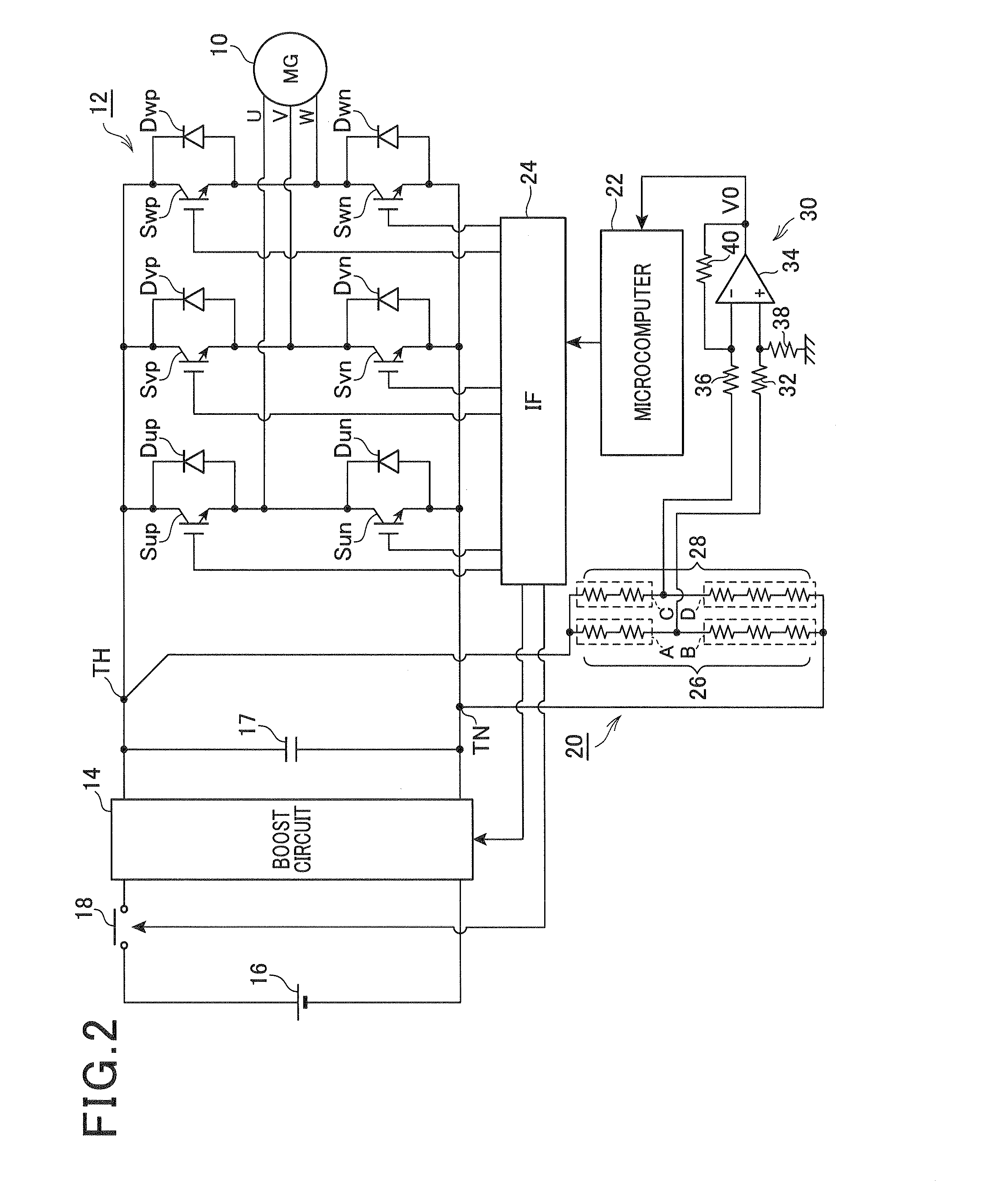
[0044]FIG. 2 schematically shows a power conversion system in accordance with the second embodiment.

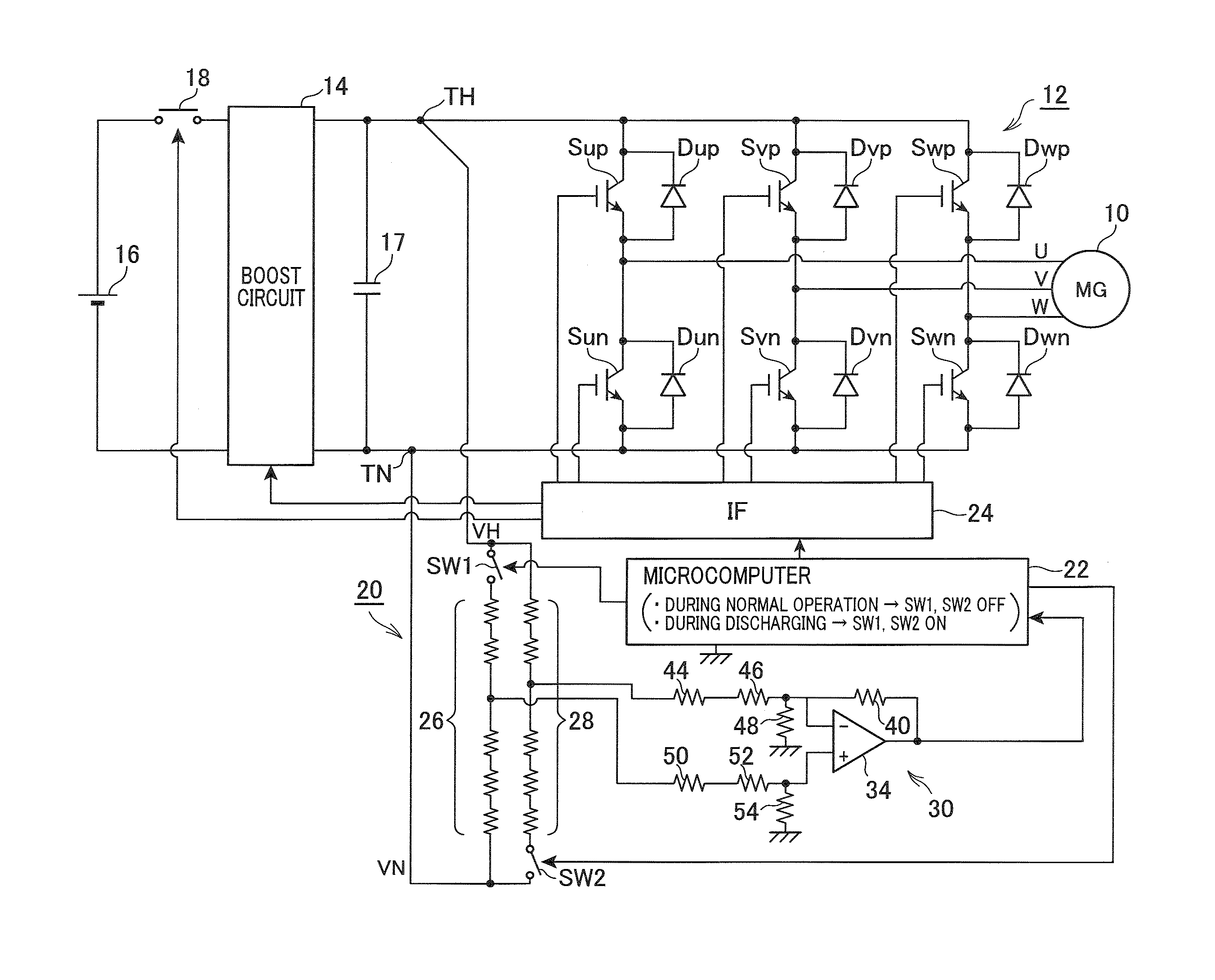
[0045]As shown in FIG. 2, a specific one of junctions of resistive elements of the high resistance resistor 26 and a specific one of junctions of resistive elements of the high resistance resistor 28 are both electrically connected to a differential amplifier circuit 30. More specifically, the nth junction of resistive elements (n=2 in the present embodiment), from the high side or from the positive input terminal TH side, of the high resistance resistor 26 that is a junction of the nth resistive element and the (n+1)th resistive element included in the high resistance resistor 26 is electrically connected to a non-inverting input terminal of the operational amplifier 34 throug...

third embodiment

[0057]There will now be explained a power conversion system in accordance with a third embodiment of the present invention. Only differences of the third embodiment from the second embodiment will be explained.

[0058]FIG. 5 schematically shows a power conversion system in accordance with the third embodiment.

[0059]In the present embodiment, the differential amplifier circuit 30 is used to perform the abnormality determination process for the parallel connection of high resistance resistors 26, 28. The differential amplifier circuit 30 is also used as voltage detection circuit to detect an input voltage of the inverter 12.

[0060]The voltage detection circuit is required for the microcomputer 22 to use the input voltage of the inverter 12 for generating an operation signal for each switching element. The voltage detection circuit converts the input voltage of the inverter 12 into a voltage that is applicable to the A / D converter in the microcomputer 22.

[0061]Since in the present embodim...


PUM


Abstract

A capacitor discharger applied to a power conversion system including a DC voltage source, a power conversion circuit having a pair of input terminals via which the DC voltage source is electrically connected to the power conversion circuit, and a capacitor electrically connected between the pair of input terminals of the power conversion circuit. The capacitor discharger includes a first series connection of resistive elements and a second series connection of resistive elements. In the capacitor discharger, a parallel connection of the first and second series connections of resistive elements is electrically connected between the pair of input terminals of the power conversion circuit. This can ensure a discharge path for discharging the capacitor even in the presence of an abnormality in a portion of the parallel connection of the first and second series connections of resistive elements.

Description

CROSS-REFERENCE TO RELATED APPLICATION[0001]This application is based on and claims the benefit of priority from earlier Japanese Patent Application No. 2011-172552 filed Aug. 8, 2011, the description of which is incorporated herein by reference.BACKGROUND[0002]1. Technical Field[0003]This invention relates to a capacitor discharger applied to a power conversion system including a direct-current (DC) voltage source, a power conversion circuit having a pair of input terminals via which the DC voltage source is electrically connected to the power conversion circuit, and a capacitor electrically connected between the pair of input terminals of the power conversion circuit.[0004]2. Related Art[0005]A power conversion system as disclosed in Japanese Patent Application Laid-Open Publication No. 2005-253276 includes a battery, an inverter, a capacitor, and a discharge resistive element, where the battery is electrically connected in parallel with the inverter, with the capacitor, and with ...

Claims


Application Information

Patent Timeline
Patent Type & Authority Patents(United States)
IPC IPC(8): H02M7/537H02M1/32H02M7/48
CPCH02M7/48H02M2001/322Y02T10/7225B60L2210/14H02M1/322Y02T10/72
Inventor WATANABE, KAZUNORIMAEBARA, TSUNEO
Owner DENSO CORP
Why Eureka
Try Eureka