LED lamp with active cooling element

a technology of active cooling element and led lamp, which is applied in the direction of indirect heat exchangers, semiconductor devices of light sources, lighting and heating apparatus, etc., can solve the problems of high inefficiency of lamps, chronic and acute poisoning, and loss of as much as 95% of input energy, so as to reduce the convective thermal resistance, enhance the convective heat transfer around elements, and increase the size of lamps or bulbs or their power consumption

Active Publication Date: 2015-01-13
IDEAL IND LIGHTING LLC
View PDF332 Cites 54 Cited by
  • Summary
  • Abstract
  • Description
  • Claims
  • Application Information

AI Technical Summary

Benefits of technology

[0017]One embodiment of a solid state light source according to the present invention comprises a light emitting diode (LED), and a heat sink with the LED in thermal contact with the heat sink. The light source further comprises an integral diaphragm or membrane pump cooling element arranged to reduce the convective thermal resistance of at least some light source elements.
[0018]One embodiment of a solid state lamp, according to the present invention comprises a plurality of LEDs and a heat sink arranged in relation to the LEDs so that the LEDs are in thermal contact with the heat sink. A diaphragm or membrane pump cooling element is included internal to the lamp and arranged flow air over surfaces of the lamp to reduce the convective thermal resistance at the surfaces.

Problems solved by technology

However, such lamps are highly inefficient light sources, with as much as 95% of the input energy lost, primarily in the form of heat or infrared energy.
One common alternative to incandescent lamps, so-called compact fluorescent lamps (CFLs), are more effective at converting electricity into light but require the use of toxic materials which, along with its various compounds, can cause both chronic and acute poisoning and can lead to environmental pollution.
While the reflective cup 13 may direct light in an upward direction, optical losses may occur when the light is reflected (i.e. some light may be absorbed by the reflective cup due to the less than 100% reflectivity of practical reflector surfaces).
In addition, heat retention may be an issue for a package such as the package 10 shown in FIG. 1a, since it may be difficult to extract heat through the leads 15A, 15B.
LED chips which have a conversion material in close proximity or as a direct coating have been used in a variety of different packages, but experience some limitations based on the structure of the devices.
Further, in such cases the phosphor can be subjected to very high concentrations or flux of incident light from the LED.
Since the conversion process is in general not 100% efficient, excess heat is produced in the phosphor layer in proportion to the incident light flux.
In compact phosphor layers close to the LED chip, this can lead to substantial temperature increases in the phosphor layer as large quantities of heat are generated in small areas.
This temperature increase can be exacerbated when phosphor particles are embedded in low thermal conductivity material such as silicone which does not provide an effective dissipation path for the heat generated within the phosphor particles.
Such elevated operating temperatures can cause degradation of the phosphor and surrounding materials over time, as well as a reduction in phosphor conversion efficiency and a shift in conversion color.
One potential disadvantage of lamps incorporating remote phosphors is that they can have undesirable visual or aesthetic characteristics.
This appearance can be considered undesirable for many applications where it can cause aesthetic issues with the surrounding architectural elements when the light is not illuminated.
This can have a negative impact on the overall consumer acceptance of these types of lamps.
Further, compared to conformal or adjacent phosphor arrangements where heat generated in the phosphor layer during the conversion process may be conducted or dissipated via the nearby chip or substrate surfaces, remote phosphor arrangements can be subject to inadequate thermally conductive heat dissipation paths.
Without an effective heat dissipation pathway, thermally isolated remote phosphors may suffer from elevated operating temperatures that in some instances can be even higher than the temperature in comparable conformal coated layers.
Stated differently, remote phosphor placement relative to the LED chip can reduce or eliminate direct heating of the phosphor layer due to heat generated within the LED chip during operation, but the resulting phosphor temperature decrease may be offset in part or entirely due to heat generated in the phosphor layer itself during the light conversion process and lack of a suitable thermal path to dissipate this generated heat.
Another issue affecting the implementation and acceptance of lamps utilizing solid state light sources relates to the nature of the light emitted by the light source itself.
Such beam profiles are generally not desired in applications where the solid-state lamp or bulb is intended to replace a conventional lamp such as a traditional incandescent bulb, which has a much more omni-directional beam pattern.
While it is possible to mount the LED light sources or packages in a three-dimensional arrangement, such arrangements are generally difficult and expensive to fabricate.
As mentioned, lamps having LED chips with a conversion material in close proximity or as a direct coating have, as well as remote conversion materials can suffer from increased temperature, particularly at high current operation.
The LED chips can also generate heat and can suffer from the detrimental effects of heat build-up.
Lamps can comprise heat sinks to draw heat away from the LED chips and / or conversion material, but even these lamps can suffer from inadequate heat dissipation.
Good heat dissipation with well controlled LED chip junction temperature presents a unique challenge for solid state lighting solutions in comparison with traditional incandescent and fluorescent lighting.
It is often the case that the convective heat dissipation into the ambient air can be the biggest thermal dissipation bottleneck of the luminaire system.
The buoyancy flow is typically very slow, especially for small sized objects.

Method used


Image

  • LED lamp with active cooling element
  • LED lamp with active cooling element
  • LED lamp with active cooling element

Examples


Embodiment Construction

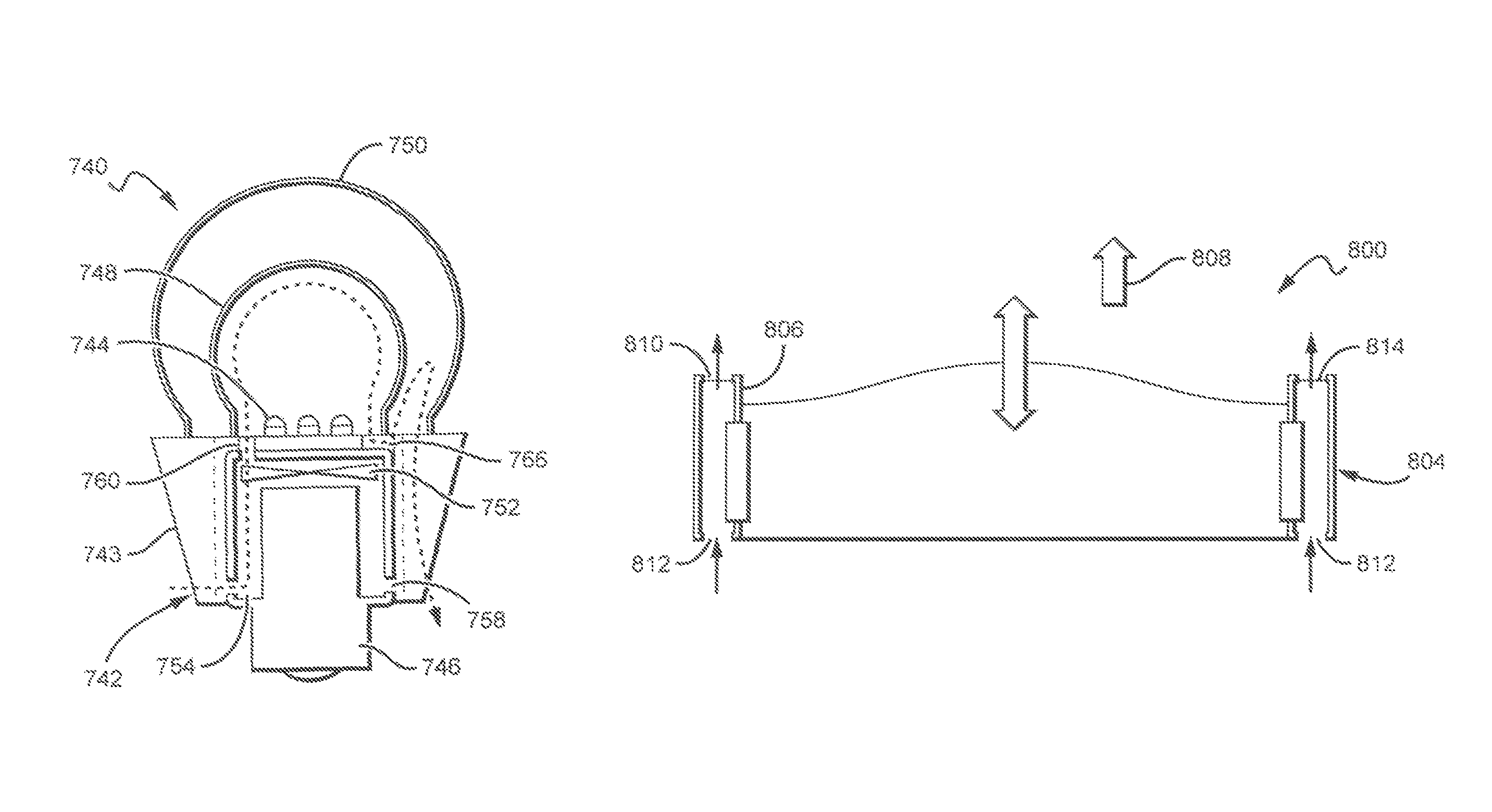
[0062]The present invention is directed to improved solid state lamp or bulb structures that are efficient, reliable and cost effective. In some embodiments, the lamps according to the present invention can provide an essentially omnidirectional emission pattern from solid state light sources, while still having features that allow the lamps and their light sources to operate at reasonable temperatures. Some lamps can have light sources that comprise directional emitting light sources, such as forward emitting light sources, with the lamps including features to disperse the directional light source to a more uniform emission suitable for lamps. To allow operation at acceptable temperatures, the lamp structures can comprise active elements to assist in thermal management of the lamp structures and to reduce the convective thermal resistance around certain of the lamp elements. Reducing thermal resistance can increase the natural heat convection away from the lamp.

[0063]Some embodimen...


PUM

PropertyMeasurementUnit
reflectivityaaaaaaaaaa

Abstract

Solid state lamp or bulb structures are disclosed that can provide an essentially omnidirectional emission pattern from directional emitting light sources, such as forward emitting light sources. The present invention is also directed to lamp structures using active elements to assist in thermal management of the lamp structures and in some embodiments to reduce the convective thermal resistance around certain of the lamp elements to increase the natural heat convection away from the lamp. Some embodiments include integral fans or other active elements such as diaphragm-pump type active cooling elements, that move air over the surfaces of a heat sink, while other embodiments comprise internal fans or other active elements that can draw air internal to the lamp. The movement of the air over these surfaces can agitate otherwise stagnant air to decrease the convective thermal resistance and increasing the ability of the lamp to dissipate heat generated during operation.

Description

[0001]This application claims the benefit of U.S. Provisional Patent Application Ser. No. 61 / 339,516, filed on Mar. 3, 2010, U.S. Provisional Patent Application Ser. No. 61 / 339,515, filed on Mar. 3, 2010, U.S. Provisional Patent Application Ser. No. 61 / 386,437, filed on Sep. 24, 2010, U.S. Provisional Application Ser. No. 61 / 424,670, filed on Dec. 19, 2010, U.S. Provisional Patent Application Ser. No. 61 / 434,355, filed on Jan. 19, 2011, U.S. Provisional Patent Application Ser. No 61 / 435,326, filed on Jan. 23, 2011, and U.S. Provisional Patent Application Ser. No. 61 / 435,759, filed on Jan. 24, 2011. This application is also a continuation-in-part from, and claims the benefit of, U.S. patent application Ser. No. 12 / 985,275, to Tong et al., filed on Jan. 5, 2011, U.S. patent application Ser. No. 12 / 848,825, filed on Aug. 2, 2010 now U.S. Pat. No. 8,562,161, U.S. patent application Ser. No. 12 / 889,719, filed on Sep. 24, 2010, and U.S. patent spplication Ser. No. 12 / 975,820, filed on Dec...

Claims


Application Information

Patent Timeline
Patent Type & Authority Patents(United States)
IPC IPC(8): F21V29/00F21K99/00F21V3/02F21V3/04F21Y101/02
CPCF21K9/135F21V29/02F21V29/405F21K9/54F21V3/02F21V3/0481F21K9/56F21Y2101/02F21V29/2231F21V29/027F21V29/025F21V29/63F21V29/673F21V29/677F21V29/773F21K9/232F21K9/62F21K9/64F21Y2115/10F21V3/12F21V29/67
Inventor TONG, TAOYOUMANS, MARKHE, YEJIN
Owner IDEAL IND LIGHTING LLC
Why Eureka
Try Eureka