Gas analysis apparatus

a technology of gas analysis and apparatus, applied in the direction of optical radiation measurement, instruments, investigating moving fluids/granular solids, etc., can solve the problems of large difference resulting from accumulation of individual differences among parts, and the output may be actually different, so as to reduce manufacturing and maintenance costs, and achieve excellent analytical accuracy.

Active Publication Date: 2015-01-13
HORIBA LTD
View PDF15 Cites 5 Cited by
  • Summary
  • Abstract
  • Description
  • Claims
  • Application Information

AI Technical Summary

Benefits of technology

[0038]According to the present invention, it is possible to provide a gas analysis apparatus, which is compact and can reduce the manufacturing cost and the maintenance cost, and have excellent analytical accuracy.

Problems solved by technology

However, the above-described gas analysis apparatus includes problems below.
In addition, the light receiving units have individual differences (differences among the devices) too, and the outputs may be actually different from each other in many cases, even though the light receiving units based on the same design are primarily intended to generate the same outputs in response to the same inputs.
Accordingly, in the signal processing result obtained based on the above-described two beams after the branch, there is a great chance of a difference resulting from the accumulation of each of the individual differences among the parts.
Accordingly, it is impossible to accurately perform the zero correction, so that it is difficult to perform a highly accurate components analysis, which is a problem.
Furthermore, it is necessary to have different systems (systems having a light receiving unit and a signal processing unit) for the two beams after the branch, so the whole analysis apparatus has to grow in size.
In addition, the heating of the systems increases the heating value of the analysis apparatus as a whole, and the durability of the signal processing circuit is deteriorated, which is a problem.
Since the gas analysis apparatus of probe type is attached to the flue for use, it is likely affected by heat of the sample gas and gets higher in temperature, so that it is likely to be deteriorated.

Method used


Image

  • Gas analysis apparatus
  • Gas analysis apparatus
  • Gas analysis apparatus

Examples


first embodiment

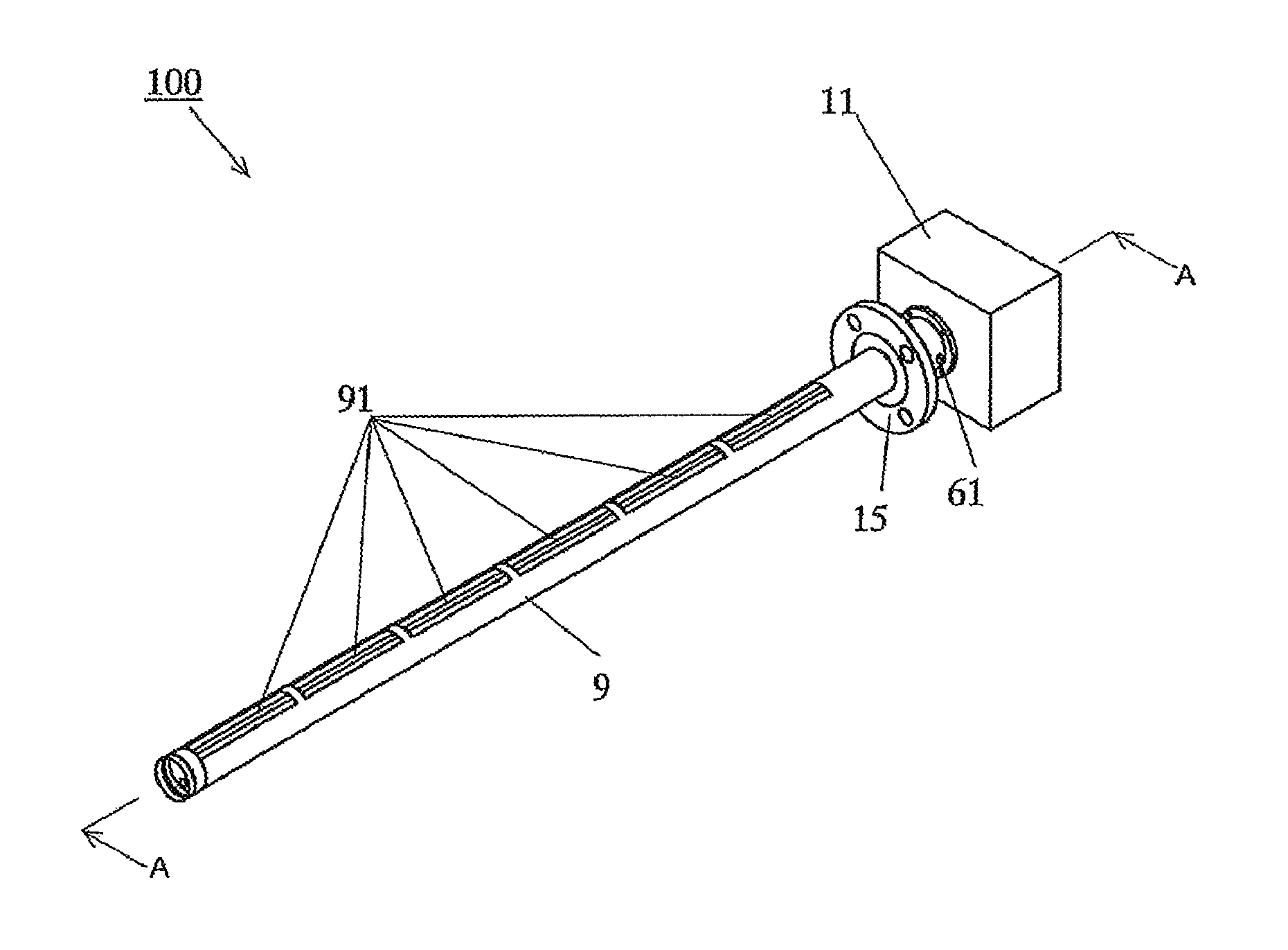
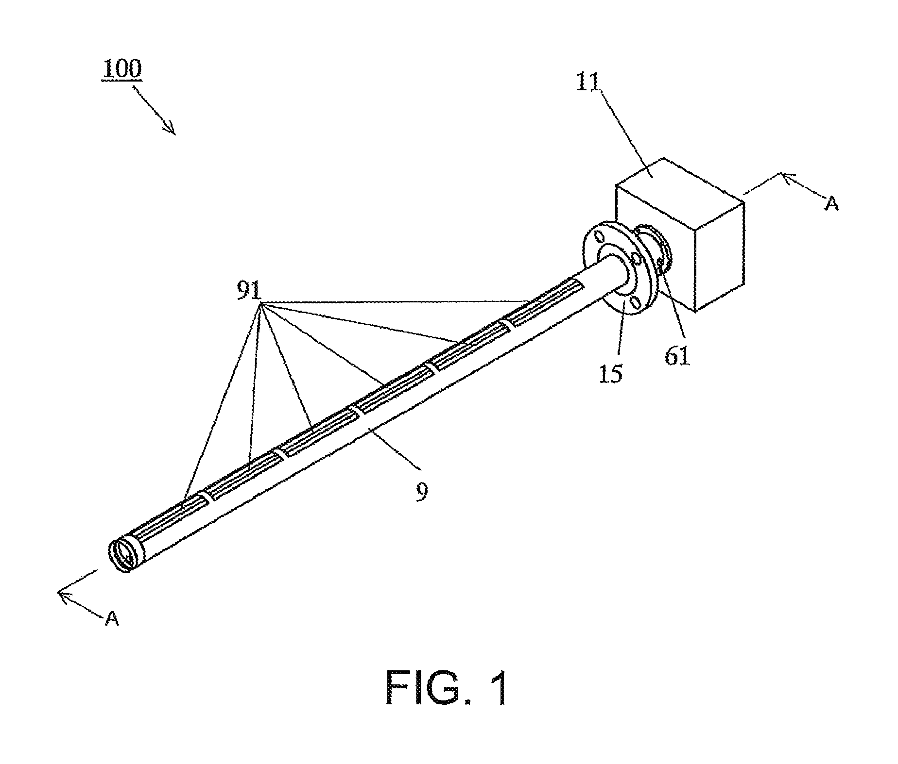
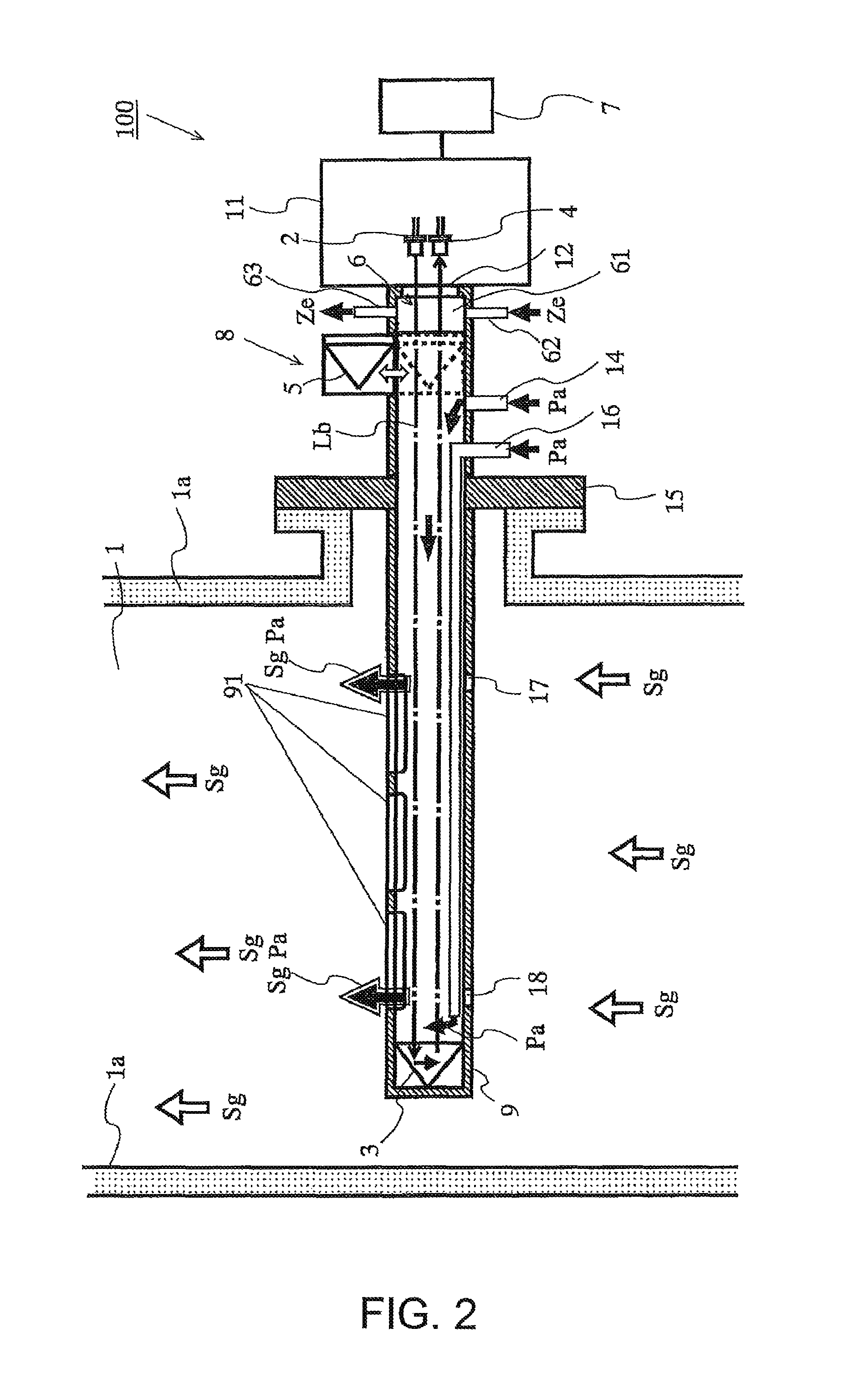
[0054]Below, a gas analysis apparatus 100 according to the first embodiment will be described. The gas analysis apparatus 100 is what is called a gas analysis apparatus of probe type. FIG. 1 is an outside view of a gas analysis apparatus according to a first embodiment. FIG. 2 is a view including A-A section of the gas analysis apparatus shown in FIG. 1, and is a view for showing the gas concentration analysis mode. FIG. 3 is a view including A-A section of the gas analysis apparatus shown in FIG. 1, and is a view for showing the correction mode or the calibration mode.

[0055]The gas analysis apparatus 100 according to the first embodiment is a gas analysis apparatus that analyzes concentration of certain components contained in the sample gas flowing into a gas flue 1. The gas analysis apparatus 100 is, for example, a non-dispersive infrared (NDIR) analyzer.

[0056]As shown in FIGS. 2, 3, the gas analysis apparatus 100 includes one light emitting unit 2, a first reflector 3, one light...

second embodiment

[0097]Below, a gas analysis apparatus 200 according to the second embodiment will be described. The gas analysis apparatus 200 is a gas analysis apparatus of what is called open path type. FIG. 8 is a sectional view for showing internal constituents of the gas analysis apparatus in the second embodiment, and is a view for showing the gas concentration analysis mode. FIG. 9 is a sectional view for showing internal constituents of the gas analysis apparatus in the second embodiment, and is a view for showing the zero correction mode. The second embodiment will be explained by mainly focusing on points different from the first embodiment. The same structure as those of the first embodiment will not be explained, while the same reference symbols are assigned.

[0098]According to the second embodiment, as shown in FIGS. 8, 9, the gas analysis apparatus 200 is constituted by a first unit 19 and a second unit 20, which are formed separately and independently. The first unit 19 is attached to...

third embodiment

[0111]Using FIG. 10 to FIG. 13, a third embodiment will be described. The third embodiment is different from the above-described embodiments only in a structure that supports the second reflector 5. FIG. 10 is a sectional view for showing a structure of the switching unit in the third embodiment, and is a view for showing the correction mode or the calibration mode. FIG. 11 is a perspective view of a bearing. FIG. 12 is a plane view of a bearing. FIG. 13 is a partial enlarged view of FIG. 10.

[0112]The second reflector 5 is supported by a mirror holder 104.

[0113]As shown in FIG. 10, in this embodiment, the back-forward moving mechanism includes a positioning mechanism 101. The positioning mechanism 101 adjusts the position of the second reflector such that the second reflector 5 has always the same direction and the same position when the air cylinder 84 places the second reflector 5 into the light path.

[0114]The positioning mechanism 101 is arranged below the second reflector 5 and ...


PUM

PropertyMeasurementUnit
concentrationsaaaaaaaaaa
optically transparentaaaaaaaaaa
cylindrical shapeaaaaaaaaaa

Abstract

A gas analysis apparatus includes: a first reflector that reflects measurement light from a light emitting unit disposed outside a gas flue wall and transmitted through a sample gas. A light receiving unit outside the gas flue wall receives measurement light reflected by the first reflector. A second reflector outside the gas flue wall reflects measurement light toward the light receiving unit. A computing unit analyzes sample gas by allowing the measurement light to be reflected by the first reflector and performs correction or calibration of the gas analysis apparatus using known substances within an associated containing unit along the light path between the light emitting unit and the second reflector by allowing measurement light to be reflected by the second reflector. A switching unit outside the gas flue wall selectively removes or inserts the second reflector from the light path during component concentration analysis and correction or calibration, respectively.

Description

CROSS REFERENCE TO RELATED APPLICATIONS[0001]This application is the U.S. national phase of PCT / JP2012 / 070461 filed Aug. 10, 2012, which claims priority to Japanese Application 1011-177339 filed Aug. 12, 2011, and Japanese Application 2011-281515 filed Dec. 22, 2011, the disclosures of which are hereby incorporated by reference in their entirety.TECHNICAL FIELD[0002]The present invention relates to a gas analysis apparatus, particularly to a gas analysis apparatus that analyzes concentration of certain components in the sample gas using an optical absorption method.BACKGROUND ART[0003]Conventionally, exhaust combustion gas, which is exhausted from a boiler that burns coal or heavy oil, includes components such as NOx, SOx, CO2, and CO. And a gas analysis apparatus has been developed that analyzes the contents of the components in the gas. As such a gas analysis apparatus, for example, an apparatus employing probe type has been developed. According to the gas analysis apparatus of pr...

Claims


Application Information

Patent Timeline
Patent Type & Authority Patents(United States)
IPC IPC(8): G01N21/61G01N21/27G01N21/35G01N21/53G01N21/85
CPCG01N21/3504G01N21/274G01N21/61G01N2021/3513G01N2021/536G01N2021/8514G01N2021/8578
Inventor IDO, TAKUYAOHNISHI, TOSHIKAZUMORI, TETSUYA
Owner HORIBA LTD
Why Eureka
Try Eureka