Radio frequency power amplifier

a power amplifier and radio frequency technology, applied in the direction of amplifiers with semiconductor devices only, amplifiers with coupling networks, amplifiers with semiconductor devices, etc., can solve the problems of fet components affecting high-efficiency operation, and achieve the effect of high pa

Active Publication Date: 2015-02-03
PANASONIC SEMICON SOLUTIONS CO LTD
View PDF20 Cites 3 Cited by
  • Summary
  • Abstract
  • Description
  • Claims
  • Application Information

AI Technical Summary

Benefits of technology

[0011]A radio frequency power amplifier according to the present invention adjusts the phase of the reflection coefficient at the second harmonic to be capacitive (greater than 180 degrees and less than 360 degrees), and adjusts the phase of the reflection coefficient at the third harmonic to be inductive (greater than 0 degrees and less than 180 degrees), in an output load circuit as seen from the output terminal of an amplifying element. Consequently, also in a case where a high-power amplifying element is used as an amplifying element, the load as seen from the drain terminal meets the class F load conditions considering the influences of the parasitic capacitance and parasitic inductance of the amplifying element, leading to high PAE.

Problems solved by technology

However, in practice, even if a class F load circuit, which short circuits the load at an even harmonic and opens the load at an odd harmonic, is provided at the output side of the FET, influences of parasitic components of the FET hinder high-efficiency operation.

Method used


Image

  • Radio frequency power amplifier
  • Radio frequency power amplifier
  • Radio frequency power amplifier

Examples


embodiment 1

(Embodiment 1)

[0048]Hereinafter, referring to the drawings, a description is given of a radio frequency power amplifier according to Embodiment 1.

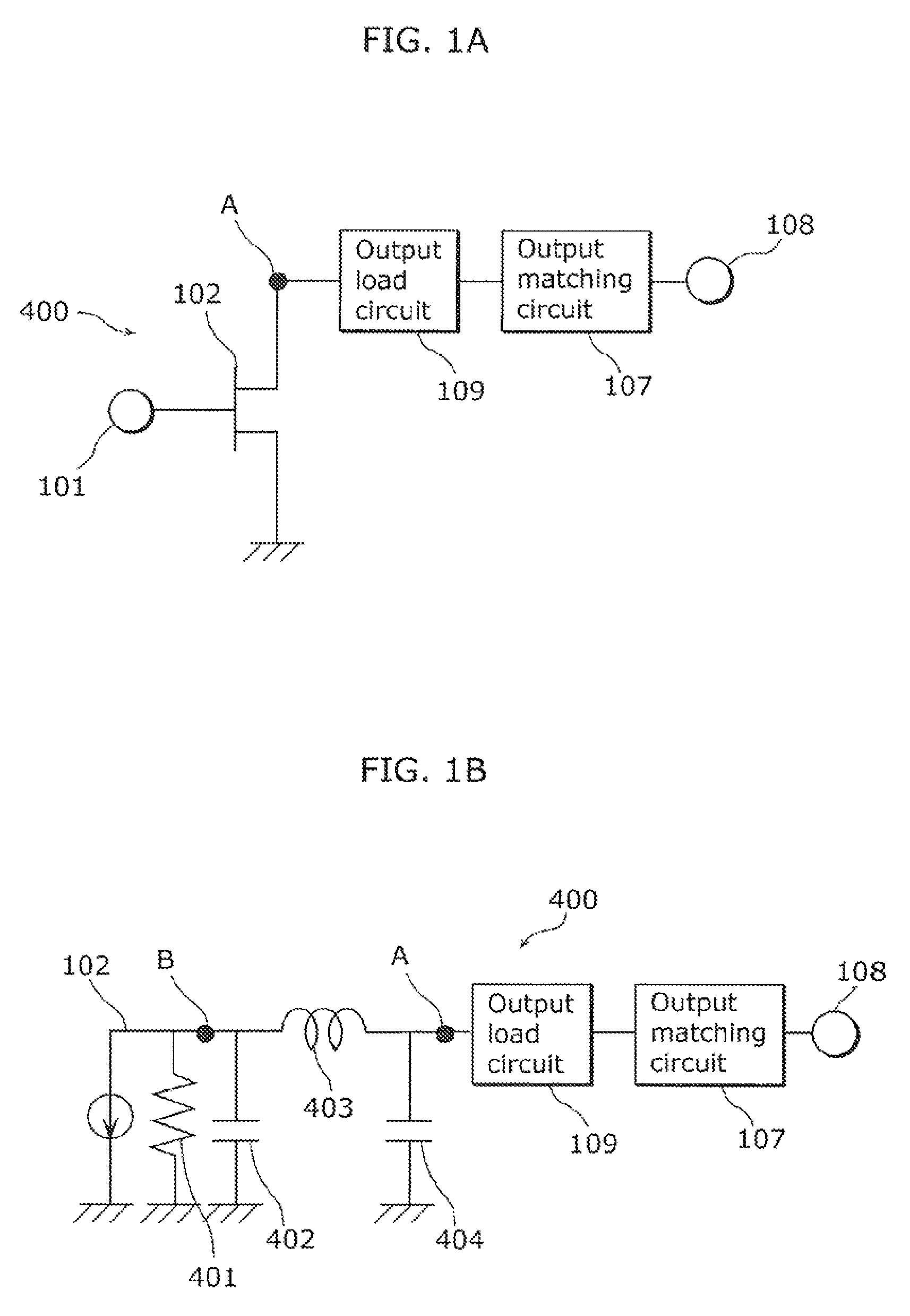
[0049]FIG. 1A is a schematic circuit diagram of a radio frequency power amplifier 400 according to Embodiment 1. FIG. 1B is an equivalent circuit diagram of the radio frequency power amplifier 400 according to Embodiment 1.

[0050]In FIG. 1A, the radio frequency power amplifier 400 includes: an amplifying element 102 (for example, FET) which amplifies a radio frequency signal that is an input signal; an output load circuit 109; and an output matching circuit 107. The radio frequency signal input from an input terminal 101 is amplified by the amplifying element 102, and is output from an output terminal 108 through the output load circuit 109 and the output matching circuit 107.

[0051]FIG. 1B is an equivalent circuit diagram where the output impedance of the amplifying element 102 in FIG. 1A is represented by an output resistance 401, a first ...

embodiment 2

(Embodiment 2)

[0072]Next, referring to the drawings, more specific descriptions are given of the circuit configuration of the radio frequency power amplifier in Embodiment 2.

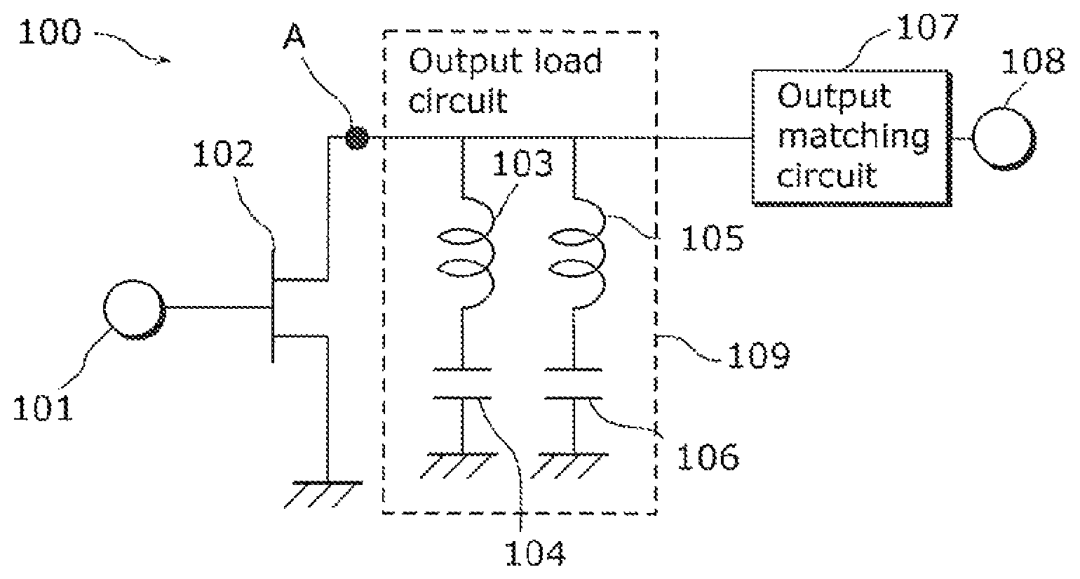
[0073]FIG. 3 is a circuit diagram of a radio frequency power amplifier 100 according to Embodiment 2.

[0074]The radio frequency power amplifier 100 in FIG. 3 includes an amplifying element 102 (for example, FET) which amplifies a radio frequency signal, an output load circuit 109, and an output matching circuit 107. The radio frequency signal input from an input terminal 101 is amplified by the amplifying element 102, and is output from an output terminal 108 through the output load circuit 109 and the output matching circuit 107.

[0075]The output load circuit 109 includes: a first series resonant circuit where an inductor 103 serving as an inductive element and a capacitor 104 serving as a capacitive element are connected in series; and a second series resonant circuit where an inductor 105 serving as an inductiv...

embodiment 3

(Embodiment 3)

[0094]Next, referring to the drawings, a description is given of another specific circuit configuration of the radio frequency power amplifier according to the present invention in Embodiment 3.

[0095]FIG. 6 is a circuit diagram of a radio frequency power amplifier 300 according to Embodiment 3.

[0096]Comparing the radio frequency power amplifier 300 in FIG. 6 with the radio frequency power amplifier 100 in FIG. 3, the output load circuit 306 has a circuit configuration different from the output load circuit 109. The other circuit configurations are the same, and thus, the same referential numerals are used and their detailed descriptions are not given.

[0097]The output load circuit 306 in FIG. 6 includes: a third series resonant circuit which includes an inductor 302 serving as an inductive element and a capacitor 303 serving as a capacitive element that are connected in series; a fourth series resonant circuit which includes an inductor 304 serving as an inductive eleme...


PUM


Abstract

A radio frequency power amplifier includes: an amplifying element which amplifies an input signal and outputs the signal from an output terminal; and an output load circuit which includes a first resonant circuit and a second resonant circuit that are connected to the output terminal. The first resonant circuit has a resonance frequency higher than the frequency of the second harmonic of the input signal, and the second resonant circuit has a resonance frequency lower than the frequency of the third harmonic of the input signal. The output load circuit has such an impedance looking from the output terminal that a phase of a reflection coefficient at the second harmonic of the input signal is greater than 180 degrees and less than 360 degrees, and a phase of a reflection coefficient at the third harmonic of the input signal is greater than 0 degrees and less than 180 degrees.

Description

TECHNICAL FIELD[0001]The present invention relates to radio frequency power amplifiers, and in particular, to a radio frequency power amplifier suitable for use as a class F amplifier circuit or an inverse class F amplifier circuit which controls harmonics.BACKGROUND ART[0002]A radio frequency power amplifier has such input and output characteristics that (i) when input power is low, a signal is amplified while maintaining constant gain in a linear region, and (ii) as the input power increases and gain begins to decrease, output power becomes constant in a saturation region regardless of the input power level.[0003]For example, a Doherty amplifier is known as a representative technique for increasing the power added efficiency (PAE) in the linear region. Furthermore, for example, a class F amplifier is known as a technique for increasing the PAE in the saturation region.[0004]A class F amplifier using a field effect transistor (FET) makes the temporal waveform of the voltage of the ...

Claims


Application Information

Patent Timeline
Patent Type & Authority Patents(United States)
IPC IPC(8): H03F3/191H03F1/02H03F1/56H03F3/193H03F3/60
CPCH03F3/193H03F1/0205H03F1/565H03F3/601H03F2200/387H03F2200/423
Inventor UNO, TAKASHIIKEDA, HIKARUYAHATA, KAZUHIROIWATA, MOTOYOSHINAITOU, HIROSHIKAMIYAMA, TOMOHIDE
Owner PANASONIC SEMICON SOLUTIONS CO LTD
Why Eureka
Try Eureka