
Smart power combiner

a power combiner and amplifier technology, applied in amplifiers, amplifiers with semiconductor devices/discharge tubes, electrical devices, etc., can solve problems such as degrading overall efficiency, affecting the performance of amplifiers, and affecting the efficiency of amplifiers, so as to reduce input and output reflection coefficients, and eliminate guesswork

Inactive Publication Date: 2015-02-10
CUBIC CORPORATION
View PDF51 Cites 20 Cited by
  • Summary
  • Abstract
  • Description
  • Claims
  • Application Information

AI Technical Summary

Benefits of technology

The present invention provides devices and methods for measuring phase differences and phase correction in power-combined power amplifiers. This solution allows for accurate and direct measurement of phase value differences, eliminating guesswork and ensuring the proper alignment of amplifiers. The invention can detect which amplifier(s) is at fault during a soft failure and provide information on load dissipation, which can be used to shut down the circuit if it is in danger of damage. The load detectors use semiconductor diodes for near-instantaneous and accurate power sensing, which provides more accurate information compared to previous devices. The invention also includes a compact output coupler with near-zero insertion loss for high-power-indicate function and quadrature or poly-phase operation using appropriate transmission line segments to reduce input and output reflection coefficients.

Problems solved by technology

(Conservation of energy demands that dissipation in isolation resistors is subtracted from the potential output power of the amplifier, thus degrading overall efficiency.)
Clearly it is undesirable to lose any efficiency points in this manner.
However, in solid-state power amplifiers, for example, often only small-signal data is known prior to assembling the amplifier, and small-signal phase may be different from large-signal phase.
Furthermore, amplifiers can change over time and temperature.
Thus, a solution provided at initial device fabrication may fail or unacceptably degrade later with amplifier change.
Also, effects of interconnects must be considered, including wirebonds and non-ideal phase performance of divider and combiner.
Enforcing narrow phase bins on a widely varying but finite population of amplifier chips can force undesirable compromises in phase alignment, particularly during a rework event where an amplifier chip must be replaced using “leftover” amplifiers.
In a similar manner, power sensing may be performed using isolation loads on hybrid couplers which include 90-degree hybrids and 180-degree hybrids; however, schemes such as these are not ideal and provide only one sense for every pair of amplifiers.
In addition, hybrid couplers are generally not applicable to direct N-way combiners.
While it is theoretically possible to perform power sensing across the isolation resistor in a Wilkinson power divider, decoupling the DC signal from the RF at this most-sensitive node in the combiner is a tricky endeavor, which would result in reduced power combining efficiency due to common-mode loading.

Method used


Image

  • Smart power combiner
  • Smart power combiner
  • Smart power combiner

Examples


Embodiment Construction

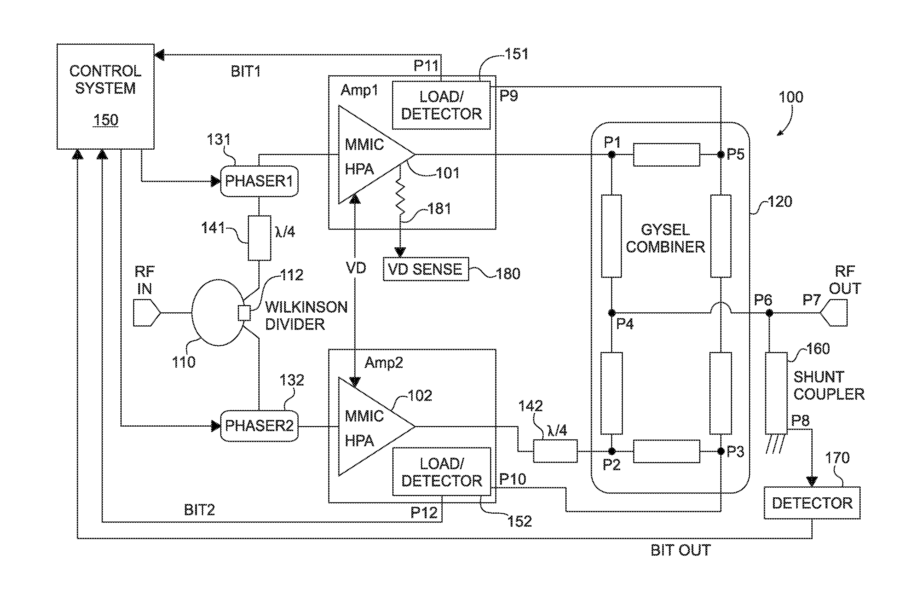
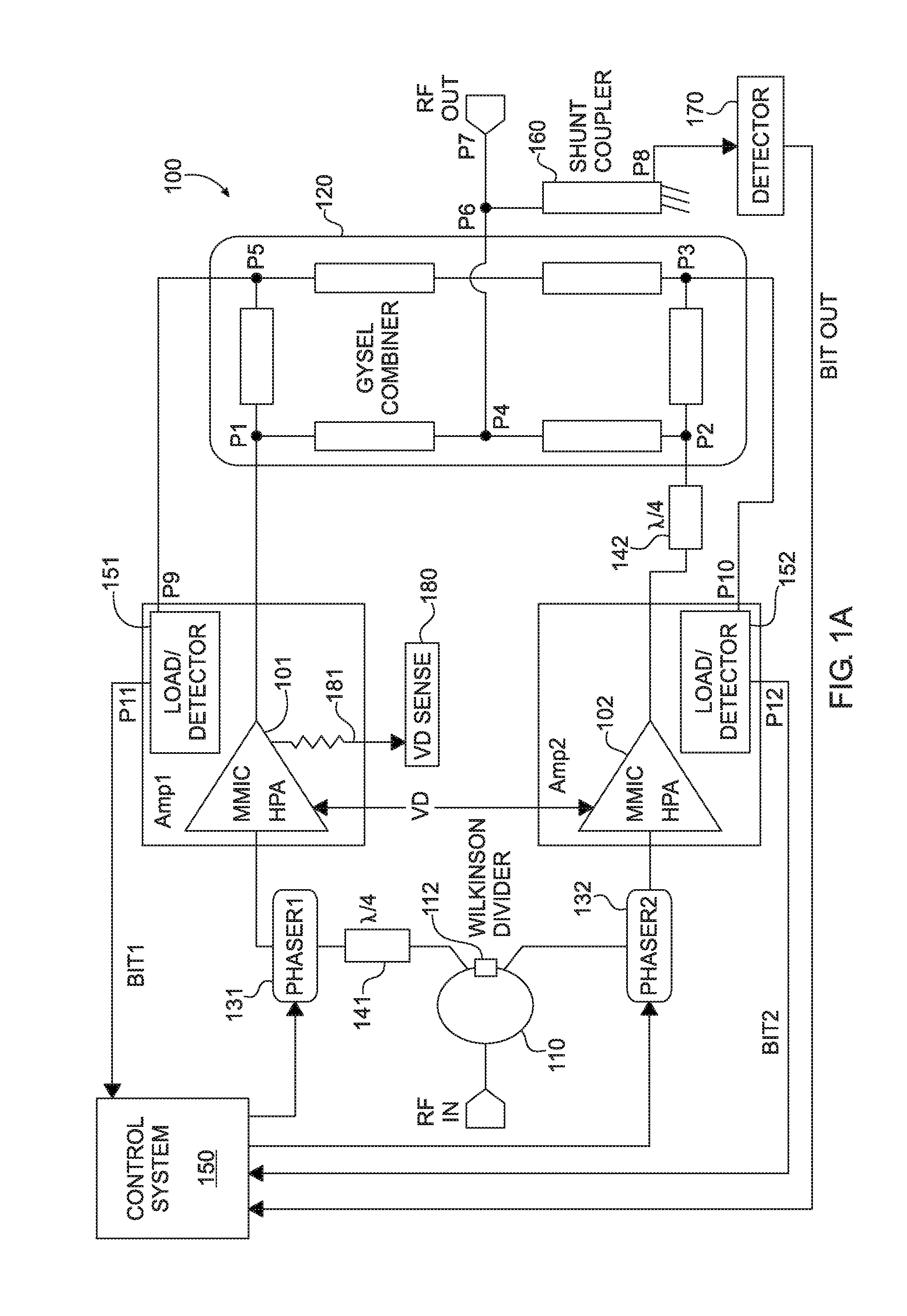
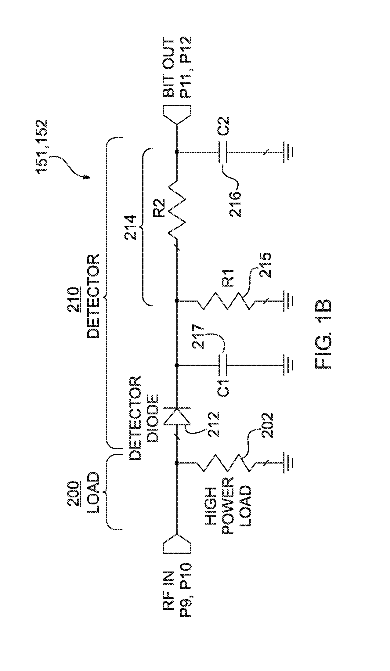
[0041]Referring now to the figures, wherein like elements are numbered alike throughout, FIG. 1A illustrates an exemplary smart power combiner 100 in accordance with the present invention which overcomes problems associated with decreased output power efficiency caused by phase mismatch between constituent amplifiers 101, 102. In one of its aspects, the devices and methods of the present invention make use of a discovery by the applicant that the magnitude and sign of the relative phase error between constituent amplifiers 101, 102 can be determined by analysis of the frequency response of load excitations of the constituent amplifiers 101, 102. That is, by measuring the excitations of at load / detectors 151, 152 relative to amplifier output power against frequency, applicant has discovered that it is possible to determine the relative phase error, if any, between the constituent amplifiers 101, 102 and to use such information to correct it. In this regard, the excitations at the loa...


PUM


Abstract

A power-combined amplifier and method are provided. In one aspect, the power-combined amplifier and method overcome problems associated with decreased output power efficiency caused by phase mismatch between constituent amplifiers.

Description

GOVERNMENT LICENSE RIGHTS[0001]This invention was made with government support under contract numbers FA9453-11-M-0062 and FA9453-12-C-0096 awarded by the Air Force Research Laboratory. The government has certain rights in the invention.FIELD OF THE INVENTION[0002]The present invention relates generally to improving the performance of power-combined amplifiers, and more particularly but not exclusively to improving the performance of power-combined solid-state power amplifiers (SSPAs) and vacuum electronics-based amplifiers.BACKGROUND OF THE INVENTION[0003]Power-combined amplifiers use a variety of technologies, including vacuum tube amplifiers such as traveling wave tubes, and solid-state amplifiers realized in GaAs, GaN, InP, SiGe, and silicon CMOS processes. There is a broad need for the ability to sense and correct transmission phases in combined amplifiers, because normal phase variations in unit amplifiers can degrade overall efficiency as some portion of the signal that shoul...

Claims


Application Information

Patent Timeline
IPC IPC(8): H03F3/68H03F1/56
CPCH03F1/56H03F1/3241H03F3/602H03F2201/3231
Inventor HUETTNER, STEVEN E.
Owner CUBIC CORPORATION
Learn More