Side shielded magnetoresistive (MR) read head with perpendicular magnetic free layer

a perpendicular magnetic and read head technology, applied in the field of read head, can solve the problems of noisy sensor, less stable sensor, and extremely unstable free layer, and achieve the effect of greater shielding effect and wide width

Active Publication Date: 2015-02-10
HEADWAY TECH INC
View PDF13 Cites 18 Cited by
  • Summary
  • Abstract
  • Description
  • Claims
  • Application Information

AI Technical Summary

Benefits of technology

[0019]A second objective of the present invention is to provide a free layer having perpendicular magnetic anisotropy (PMA) to achieve FL magnetic biasing with an intrinsic anisotropy field thereby eliminating the need for a permanent magnet hard bias and the side shield-HB coupling effects on FL layer stability.
[0021]Another objective of the present invention is to achieve minimal coupling between side shield edges and free layer edges by employing a free layer with PMA.
[0022]Another objective of the present invention is to provide a MR sensor structure in accordance with the previous objectives that has high performance, a TMR junction, and is capable of being fabricated with existing materials and processes.
[0026]In a second embodiment, the sensor stack is formed with the same configuration on the bottom shield as in the first embodiment. However, after the photoresist patterning step, the etch process extends a substantial distance into the bottom shield to generate a pedestal portion of the bottom shield below the sensor stack. Moreover, the pedestal portion of the bottom shield preferably has a greater width than the sensor stack width. Thus, the sensor stack may have a sidewall that is essentially perpendicular to the bottom shield while the sidewall formed along the pedestal portion has a less vertical slope. Preferably, a conformal insulation layer is deposited along the sidewalls of the sensor stack and bottom shield and on horizontal portions of the bottom shield. Thereafter, the photoresist is stripped and the top shield is deposited on the insulation layer including along the sidewall of the bottom shield. Thus, the top shield extends below a plane that includes the interface between the seed layer and bottom shield to provide a greater shielding effect on the free layer.

Problems solved by technology

Unfortunately, a thinner HB structure 4 will lead to a weaker pinning field on edges of free layer 11 and will yield a less stable sensor.
The most obvious draw back of this design is that top shield portion 50a is brought quite close to the HB structure 48 such that HB to top shield coupling will reduce the HB stabilizing field 48a on free layer edges 45 significantly and cause the free layer to be extremely unstable and thereby produce a noisy sensor.
In addition to the presence of a hard bias structure being a limiting factor in further reducing read gap spacing and sensor track width, the free layer is another contributor to instability at narrow sensor width, especially when a side shield is employed.
As a result, the FL edge is not well pinned and undesirable magnetization fluctuations from thermal excitation will occur as described by Y. Zhou in “Thermally Excited Low Frequency Magnetic Noise in CPP structure MR heads”, IEEE Trans. Magn., vol.
This coupling will lead to more free layer instability.
41, pp 707 (2005), a magnetic sensor with a free layer having PMA is discussed but is focused primarily on the FL material properties and does not propose any viable sensor structure.
However, an intrinsic flaw of this design is that FL 65 is deposited on the junction layer which is not feasible with TMR sensors having an oxide junction layer since there must be a magnetic layer abutting the junction layer to realize a high MR signal.
When a FL with PMA is formed directly on an oxide layer such as junction layer 64, it is difficult to achieve good PMA.
A buffer / seed layer is typically required to establish PMA in an overlying FL but the buffer / seed layer is non-magnetic and cannot produce a high MR ratio as mentioned previously.

Method used


Image

  • Side shielded magnetoresistive (MR) read head with perpendicular magnetic free layer
  • Side shielded magnetoresistive (MR) read head with perpendicular magnetic free layer
  • Side shielded magnetoresistive (MR) read head with perpendicular magnetic free layer

Examples


Embodiment Construction

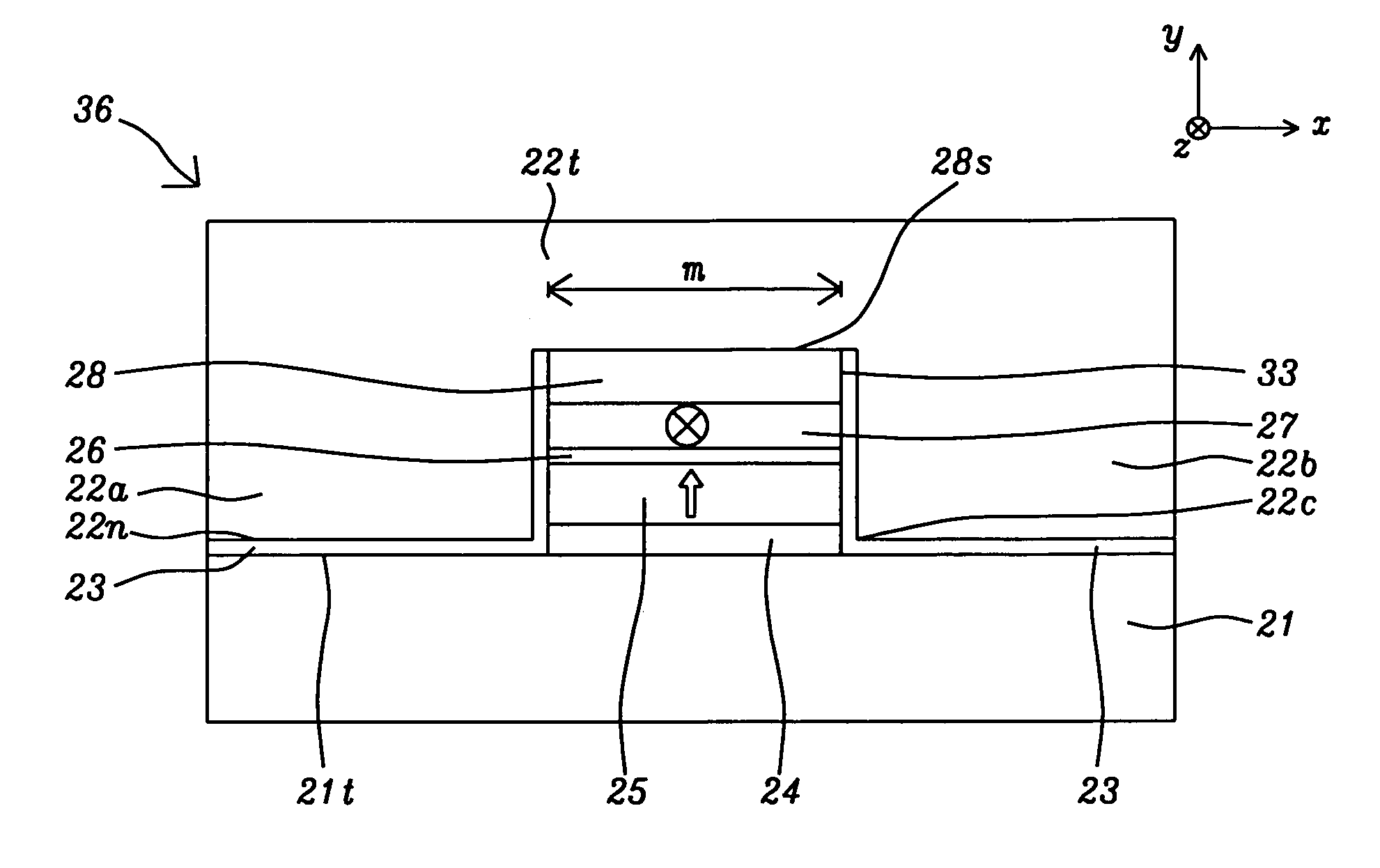
[0039]The present invention is a magnetoresistive (MR) read head in which a sensor stack has a top spin valve configuration and a self-biasing free layer with PMA that can achieve narrow stack width and a narrow read gap without the need for stabilization from a permanent hard bias structure. The sensor stack design is compatible with a variety of surrounding shield structures that include full and extended side shields. Although the preferred embodiments include a TMR sensor configuration, the sensor stack may also have a CPP GMR or CCP-CPP GMR configuration. The present invention also includes a method of forming the MR read heads as described herein.

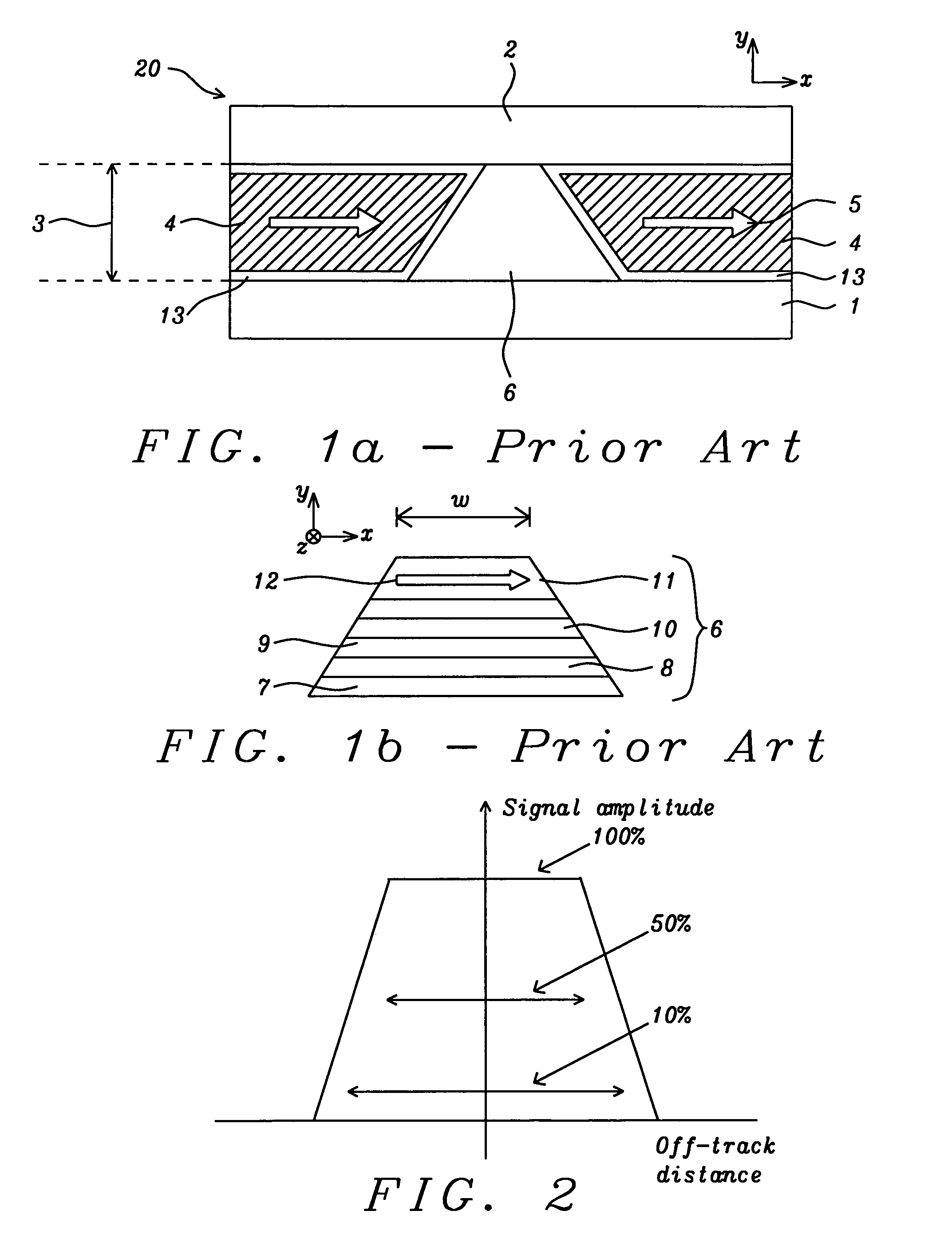
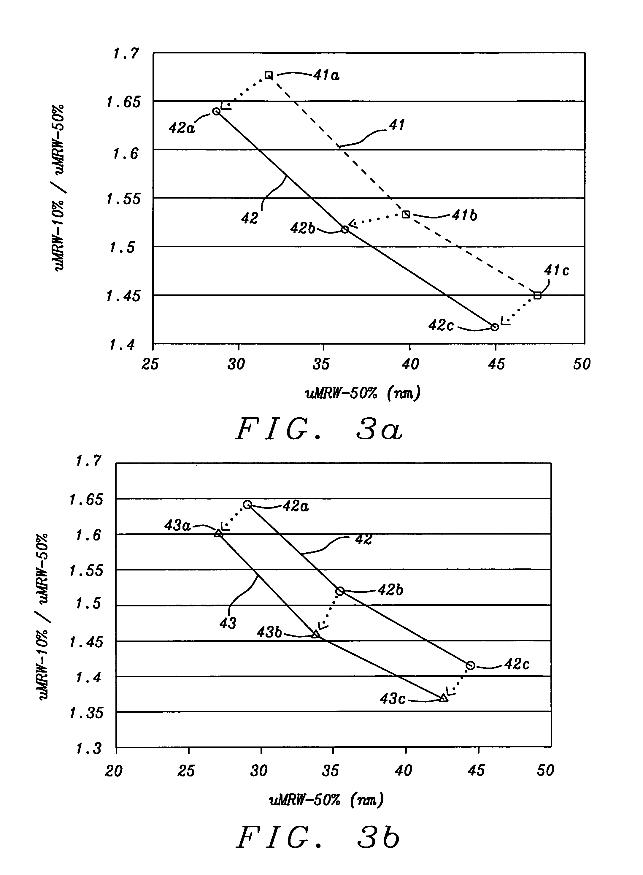
[0040]In related patent application Ser. No. 12 / 589,614, we disclosed the advantages of Co / Ni multilayer structures and the like having high PMA in CPP-TMR sensors where the magnetic anisotropy of a (Co / Ni)X laminated structure arises from the spin-orbit interactions of the 3d and 4s electrons of Co and Ni atoms. Such interaction caus...


PUM

PropertyMeasurementUnit
magnetizationaaaaaaaaaa
magnetic anisotropyaaaaaaaaaa
magnetic fieldaaaaaaaaaa

Abstract

A MR sensor is disclosed that has a free layer (FL) with perpendicular magnetic anisotropy (PMA) which eliminates the need for an adjacent hard bias structure to stabilize free layer magnetization and minimizes shield-FL interactions. In a TMR embodiment, a seed layer, free layer, junction layer, reference layer, and pinning layer are sequentially formed on a bottom shield. After patterning, a conformal insulation layer is formed along the sensor sidewall. Thereafter, a top shield is formed on the insulation layer and includes side shields that are separated from the FL by a narrow read gap. The sensor is scalable to widths<50 nm when PMA is greater than the FL self-demag field. Effective bias field is rather insensitive to sensor aspect ratio which makes tall stripe and narrow width sensors a viable approach for high RA TMR configurations. Side shields may be extended below the seed layer plane.

Description

RELATED PATENT APPLICATION[0001]This application is related to the following: U.S. Pat. No. 8,184,411; assigned to the same assignee and herein incorporated by reference in its entirety.FIELD OF THE INVENTION[0002]The invention relates to a read head in which a sensor has a top spin valve configuration with a bottom free layer that is self biasing through intrinsic perpendicular magnetic anisotropy (PMA) so that a hard bias layer is not needed for stabilization thereby enabling a narrow track width and minimal interaction with side shields for high density applications.BACKGROUND OF THE INVENTION[0003]As the data areal density in hard disk drives (HDD) continuously increases because of technology improvements, the MR sensor that is used as the read-back element in HDD is required to have increasingly better special resolution while maintaining a reasonable signal-to-noise ratio (SNR). The sensor is a critical component in which different magnetic states are detected by passing a sen...

Claims


Application Information

Patent Timeline
Patent Type & Authority Patents(United States)
IPC IPC(8): G11B5/39B82Y10/00B82Y25/00B82Y40/00G01R33/09H01F10/30H01F10/32H01F41/30
CPCB82Y40/00G11B5/3909B82Y10/00B82Y25/00G01R33/093G01R33/098G11B5/3912H01F10/30H01F10/3286H01F41/307G11B5/3906G11B2005/3996H01F10/3295H01F10/3259G11B5/398H10N50/10H10N50/80
Inventor ZHOU, YUCHENZHANG, KUNLIANGBAI, ZHIGANG
Owner HEADWAY TECH INC
Why Eureka
Try Eureka