VTOL propulsion for aircraft

a technology for aircraft and propellers, applied in the field of vtol propulsion for aircraft, can solve the problems of stymieing the development of lightweight remotely controlled aircraft, difficulty in achieving hover, and challenges for radio-control pilots

Active Publication Date: 2015-02-24
CONCEPT AIRCRAFT LLC
View PDF54 Cites 26 Cited by
  • Summary
  • Abstract
  • Description
  • Claims
  • Application Information

AI Technical Summary

Benefits of technology

[0016]The wing attaches to the body by a pin connection through the front sub-frame mount and by screws to the rear sub-frame plank mounts. The pin-screw connection enables stability using a carbon fiber reinforced Styrofoam wing. The wing includes the hover control assemblies, air source vent connections and servo actuators.

Problems solved by technology

Further, ducted-fan models have many of the flight characteristics of full-size jet aircraft, offering new challenges to radio-control pilots.
Difficulties in achieving hover to horizontal flight have, for the most part, stymied the developers of lightweight remotely controlled aircraft.
Though conquering transitory flight, the Grumman project did not provide aircraft modelers with a workable R / C power plant for internal mounting in made-to-scale fighter aircraft models.

Method used


Image

  • VTOL propulsion for aircraft
  • VTOL propulsion for aircraft
  • VTOL propulsion for aircraft

Examples


Embodiment Construction

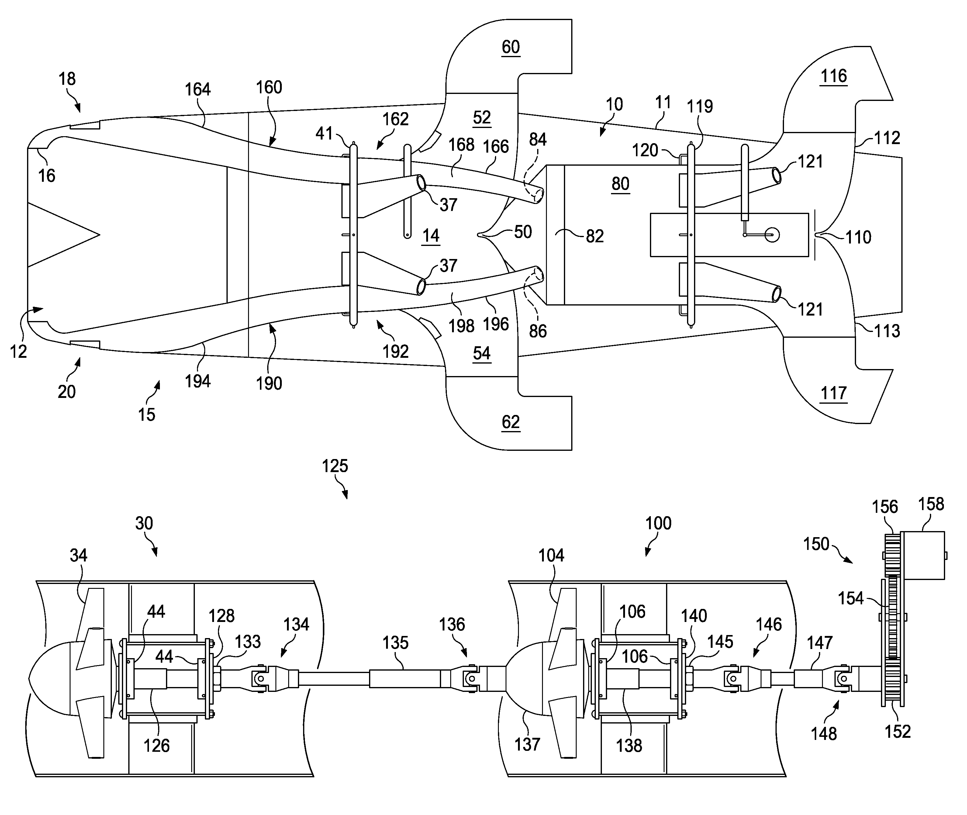
[0038]The basic system of the invention includes two fans, a drive train assembly, two thrust vectoring chambers, four nozzles, and an intake shroud. Each component adjoins to other units to make up a compressor. Each unit is individualized to perform specific tasks or operations. All the sub systems interact to control the compressor operation during hover and forward flight.

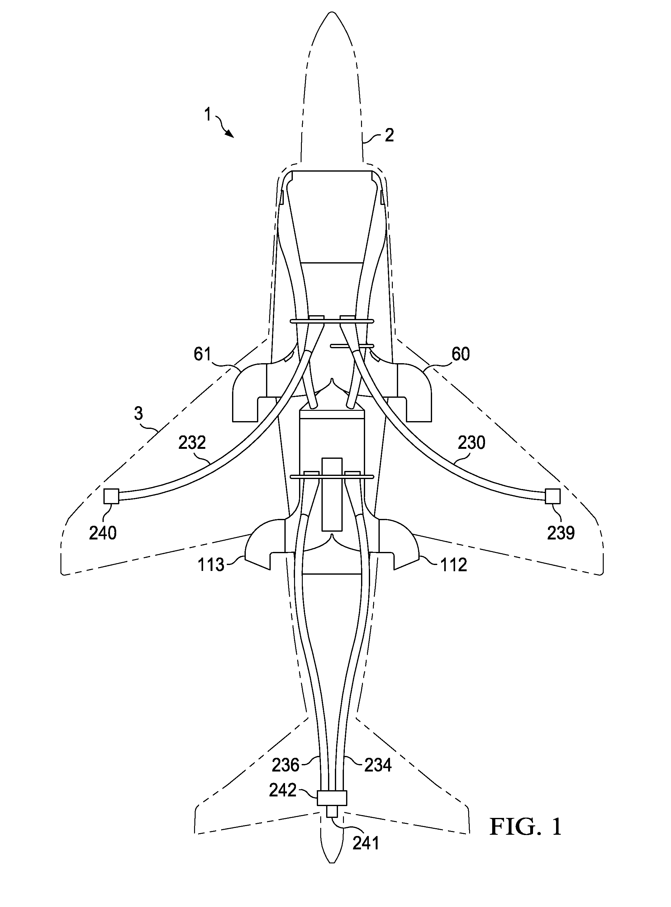
[0039]Referring first to FIG. 1, shown is a plan view of a typical aircraft 1. Aircraft 1 has a fuselage 2, wing section 3, and tail section 4. A casing 10 is located with the fuselage 2 for compressing and directing airflow.

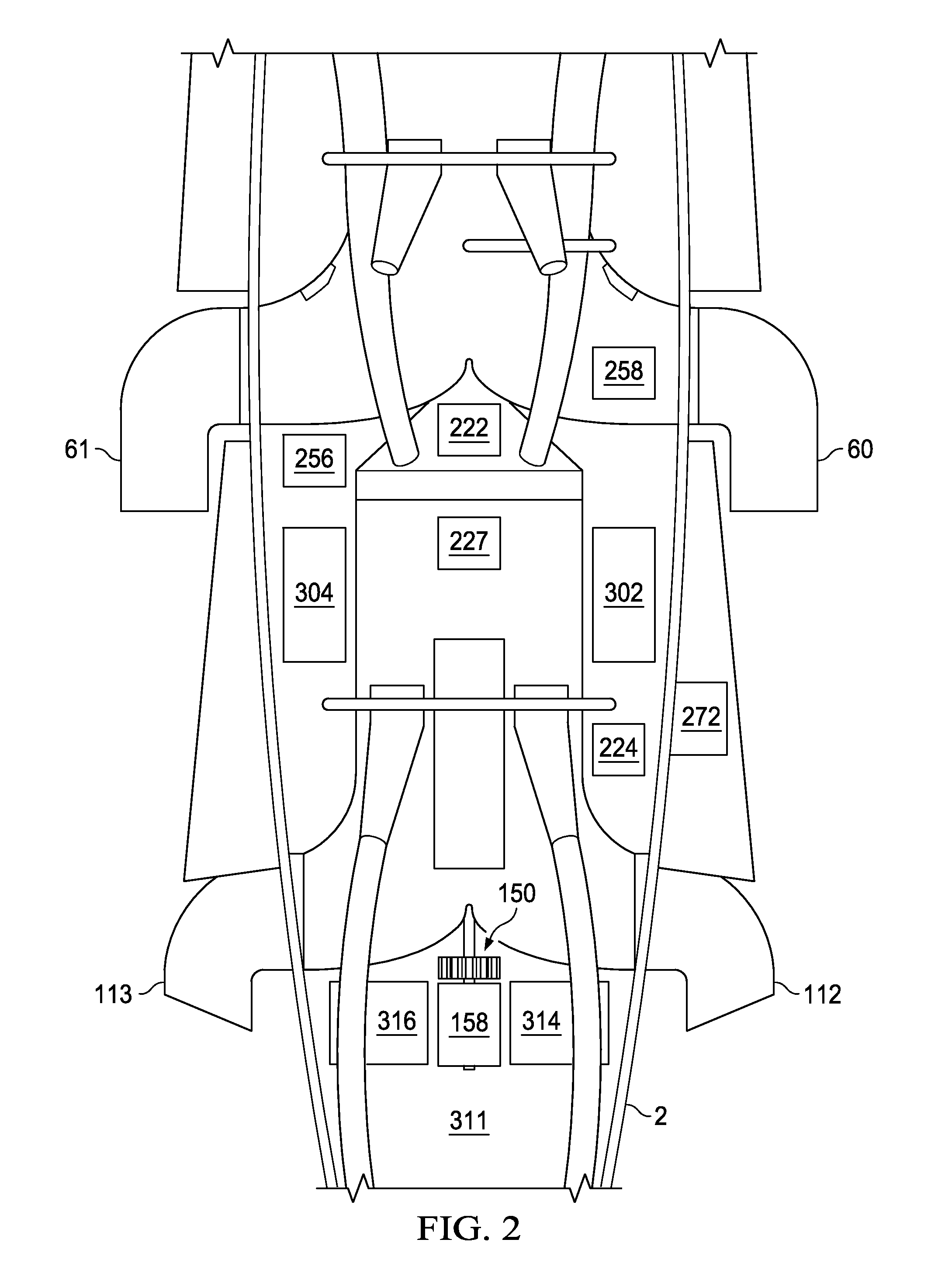
[0040]FIG. 2 shows a plan view of the interior of fuselage 2 after wing section 3 is removed. Visible is casing 10 and various components to be discussed hereafter.

[0041]Casing 10 is located within subframe 11. Referring now to FIGS. 3-5, casing 10 defines an intake shroud 12 on a front end. Casing 10 further defines a first duct chamber 14 that tapers from front to back.

[0042]Bypass duct a...


PUM


Abstract

An aircraft, such as a radio controlled aircraft, capable of vertical take-off and landing. The aircraft has a compressor in a fuselage that contains an interconnected first and second fans driven by a motor. An intake provides air to the first fan, while a bypass duct directs airflow to the second fan. Air flow from the first fan to the second fan is controlled by a valve, which is operated in tandem with doors in the bypass duct. Nozzles direct air flow out of the compressor in a selected one of a vertical or non-vertical direction for conventional flight or for hover. Hover tubes are provided to adjust the aircraft in pitch, yaw and roll. The hover tubes operate simultaneously with conventional flight controls.

Description

CROSS REFERENCE TO RELATED APPLICATIONS[0001]This application claims the priority of U.S. Provisional Patent Application No. 61 / 509,480 entitled “VTOL PROPULSION FOR UAV,” filed Jul. 19, 2011, the contents of which are hereby incorporated by reference.FIELD OF THE INVENTION[0002]An improved Hover˜Jet VTC with design features to improve efficiency.BACKGROUND OF THE INVENTION[0003]Previous design components for a hover jet VTC were articulated in U.S. Pat. No. 5,666,803, which is hereby incorporated by reference.[0004]Vertical and / or short take-off and landing (V / STOL) is a term used to describe airplanes that are able to take-off or land vertically or on short runways. Vertical takeoff and landing (VTOL) describes craft that do not require runways at all. Generally, a V / STOL aircraft needs to be able to hover.[0005]The ability for a V / STOL aircraft to hover relies on an ability to manipulate forces for roll, yaw, and pitch. An ability to control roll, yaw and pitch while hovering is ...

Claims


Application Information

Patent Timeline
Patent Type & Authority Patents(United States)
IPC IPC(8): B64C29/00B64D35/00B64D33/02
CPCB64D35/00B64C2203/00A63H27/06B64C29/0025A63H30/04B64U50/14
Inventor WINDISCH, D. ANTHONY
Owner CONCEPT AIRCRAFT LLC
Why Eureka
Try Eureka