
Solid-state lighting troffer with readily retrofittable structure

a solid-state lighting and retrofittable technology, applied in the direction of lighting support devices, light source combinations, built-in power, etc., can solve the problems of poor lighting quality, affecting mood, user eyes uncomfortable, etc., to reduce glare, improve cut-off, and facilitate mounting

Inactive Publication Date: 2015-02-24
ALEDDRA INC
View PDF8 Cites 5 Cited by
  • Summary
  • Abstract
  • Description
  • Claims
  • Application Information

AI Technical Summary

Benefits of technology

This solution provides uniform and consistent light intensity and color hue, reduces installation and maintenance costs, improves thermal efficiency, and meets current and future energy standards while ensuring reliable emergency lighting.

Problems solved by technology

The shortcomings are pixelation, glare, and not enough cut-off at vertical angles greater than 80° above the lamp nadir, which cause users' eyes uncomfortable, thus affecting their mood.
Similarly, many conventional LED troffers adopt direct illumination approach and show a poor lighting quality such as hot and dark spots and shadows.
Thus, the design not only looks unaesthetic but shows a dark stripe in the central region.
Moreover, because the heat dissipation area of the heat sink is limited, a heat sink with fins must be used to efficiently dissipate the heat generated by operating LEDs, or premature failure of the LEDs occurs.
Such kinds of design are expensive because an extra heat sink with heat-dissipation fins is needed.
Furthermore, their thermal performance is far from ideal because heat goes up, but the heat sink with fins is in the opposite downward direction, thus affecting convective heat transfer in ambient air.
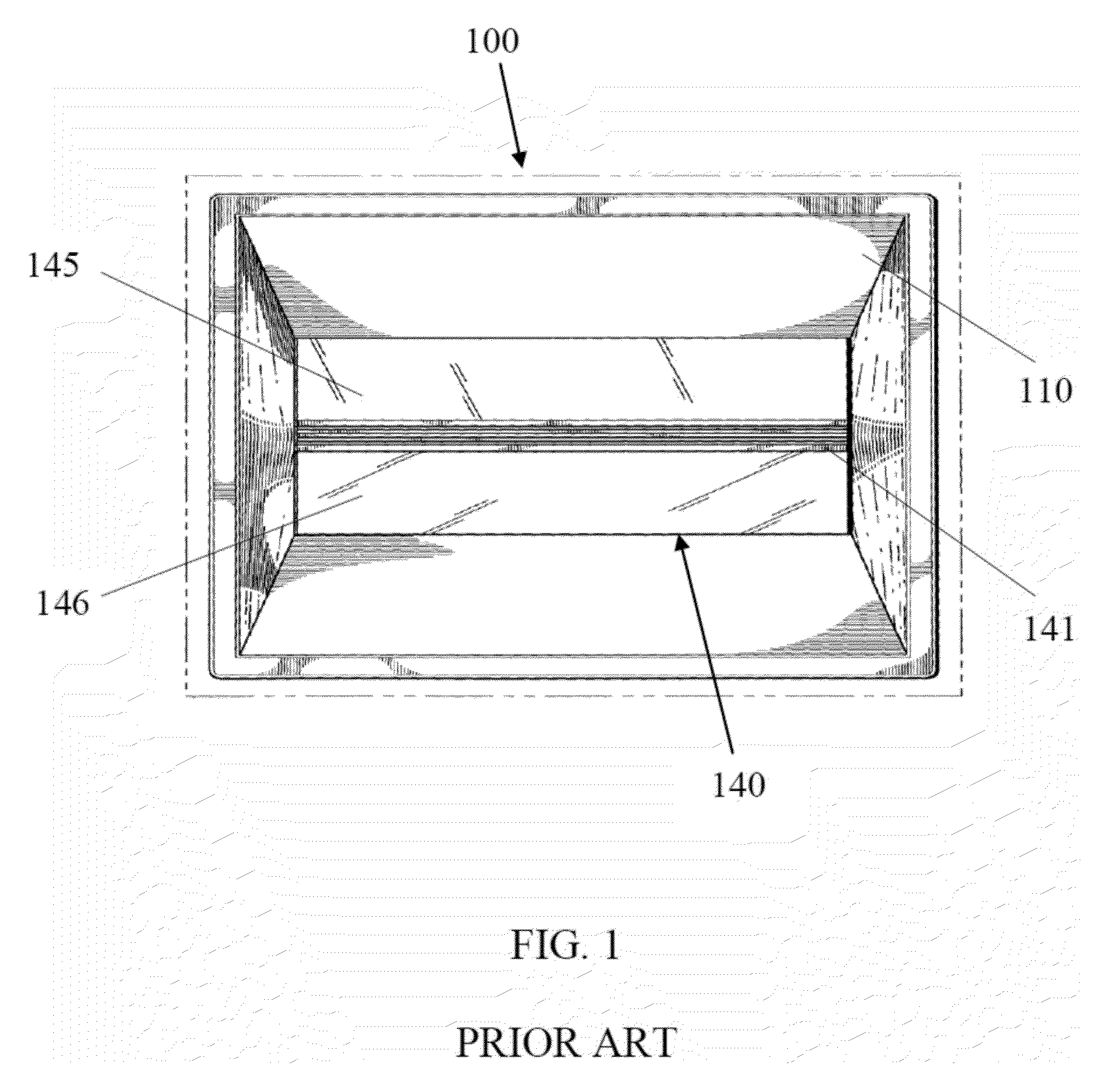
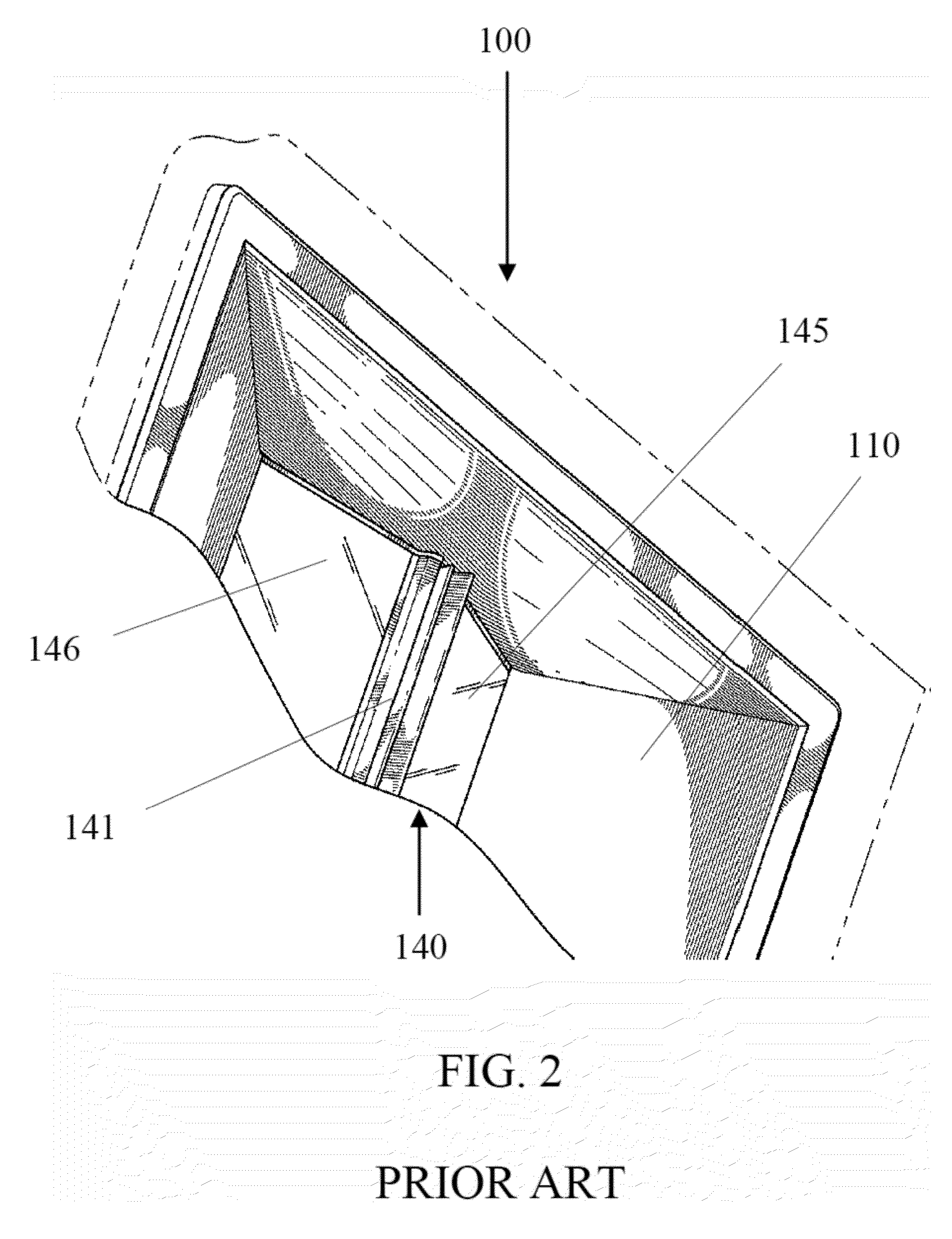
Thus, occupants in the room can see the whole bare bright area 2 by 2 feet and feel uncomfortable because a direct glare affects their eyes and distracts them.
The LED panel light troffers do not have a proper structure to sufficiently perform spatial color mixing, which makes it difficult for them to be successful on the market.
Because at the two color extremes, only one kind of LEDs emits the light, such troffers have poor cost efficiency and luminous efficacy.
Because of low luminous efficacy and difficulty to meet CIE 1931 recommendations for general lighting in solid state lighting products, such as stabilizing a specific chromaticity over time while LED junction temperatures change from ambient temperature to 120° C. or higher due to different thermal dependencies for an individual LED, the RGB approach is seldom adopted as in general lighting applications today.
Thus uniformity of the resultant CCT light and color hue within viewing angles becomes an issue if the troffer used cannot provide adequate light averaging and mixing functions.
As LED technologies and standards continue to develop rapidly, today's 2 by 4 troffer requirements of an LED luminous efficacy of 65 lumens per watt and a color rendering index (CRI) of 80 will become unsatisfactory tomorrow to consumers and the Energy Star program.
To retrofit a conventional LED troffer for replacing an existing LED driver or LED module, however, is not easy because one must first remove the whole troffer from T-bar ceiling grids.
Meeting OSHA requirements takes time and investment, but not meeting them could result in fines and even prosecution.
Currently no manufacturers have adopted the idea in an architectural troffer used to replace conventional fixtures for fluorescent lamps.
Furthermore, installing such a troffer on T-bar ceiling grids cannot be done by just one person because it is too heavy and has a dimension of 2 by 4 feet.
Installation cost becomes an issue.

Method used


Image

  • Solid-state lighting troffer with readily retrofittable structure
  • Solid-state lighting troffer with readily retrofittable structure
  • Solid-state lighting troffer with readily retrofittable structure

Examples


Embodiment Construction

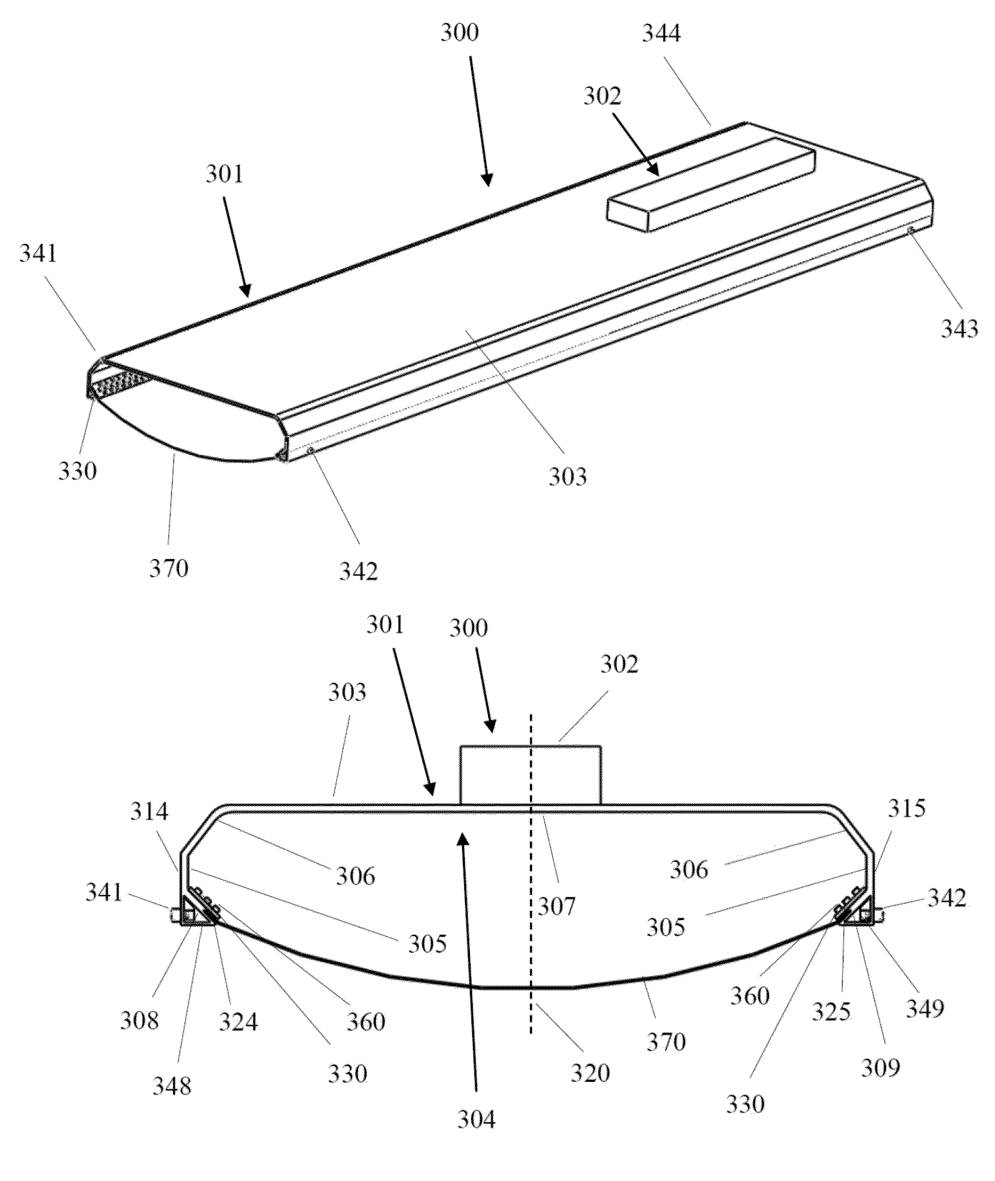
[0044]FIG. 5 is an LED light engine 300 according to the present invention. FIG. 6 is the front view of the LED light engine 300. Referring to FIGS. 5 and 6, the LED light engine 300 comprises an LED module 301 and an external driver 302. The external driver 302 may or may not be mounted on the LED module 301, although it is so shown. In other words, the external driver 302 should not be limited to this configuration only. The LED module 301 comprises an elongated body 303 comprising a reflector 304 on a surface thereof, the body having two side surface portions 314 and 315; two flat mount surface portions 324 and 325 symmetrically arranged about a central vertical plane 320, respectively connecting to the side surface portions 314 and 315 of the elongated body 303; two LED light strips 330 respectively mounted on the two flat mount surface portions 324 and 325, facing the reflector 304 with an angle less than 90° but greater than 0° as measured from their respective normal lines, e...


PUM


Abstract

A light-emitting diode (LED) troffer adopts LED light sources mounted along two lengthwise sides of an LED module that uses a reflecting diffuser and a diffused light exit window to sufficiently average white light emissions from a plurality of LEDs or to properly mix light emissions from white LEDs at correlated color temperature (CCT) of 6,200±300 K with emissions from LEDs having saturated colors for uniform and tunable CCT light outputs having a consistent intensity or color hue within viewing angles. The troffer adopting a retrofittable design enables single person to readily hang and secure the LED module single-ended on top of the troffer for installation, retrofit, and inspection. The troffer uses such an integrated LED module with a power density less than 0.0127 W / cm2, and thus no apparent heat sink is needed.

Description

BACKGROUND OF THE INVENTION[0001]1. Field of the Invention[0002]This invention relates to a light-emitting diode (LED) troffer, and more particularly to a readily retrofittable LED troffer that adopts LED light sources mounted along two lengthwise sides of an LED module and a reflecting diffuser used to sufficiently mix and uniform light emissions from various LED light sources with consistent intensity and color hue within viewing angles and improved aesthetic perception.[0003]2. Description of the Related Art[0004]Solid-state lighting from semiconductor light-emitting diodes (LEDs) has received much attention in general lighting applications today. Because of its potential for more energy savings, better environmental protection (with no hazardous materials used), higher efficiency, smaller size, and longer lifetime than conventional incandescent bulbs and fluorescent tubes, the LED-based solid-state lighting will be a mainstream for general lighting in the near future. Meanwhile,...

Claims


Application Information

Patent Timeline
Patent Type & Authority Patents(United States)
IPC IPC(8): F21S4/00F21K99/00
CPCF21K9/17F21K9/54F21S8/00F21S9/022F21V7/0008F21Y2113/00F21Y2103/10F21Y2115/10F21Y2113/17
Inventor HSIA, CHUNGHOSHEN, PAI-SHENGYU, CHUNTE
Owner ALEDDRA INC
Learn More