
Timing module

a technology of timing module and time delay, which is applied in the direction of time interval measurement, combustion ignition, combustion process, etc., can solve the problems of compromising blasting effectiveness, high and a large part of the overall cost of the system, and achieves the effect of not compromising blasting effectiveness or jeopardising the cost of copper conductors

Active Publication Date: 2015-03-03
DETNET SOUTH AFRICA (PTY) LTD
View PDF17 Cites 20 Cited by
  • Summary
  • Abstract
  • Description
  • Claims
  • Application Information

AI Technical Summary

Benefits of technology

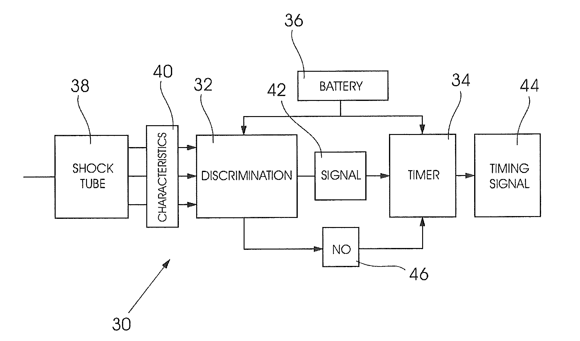
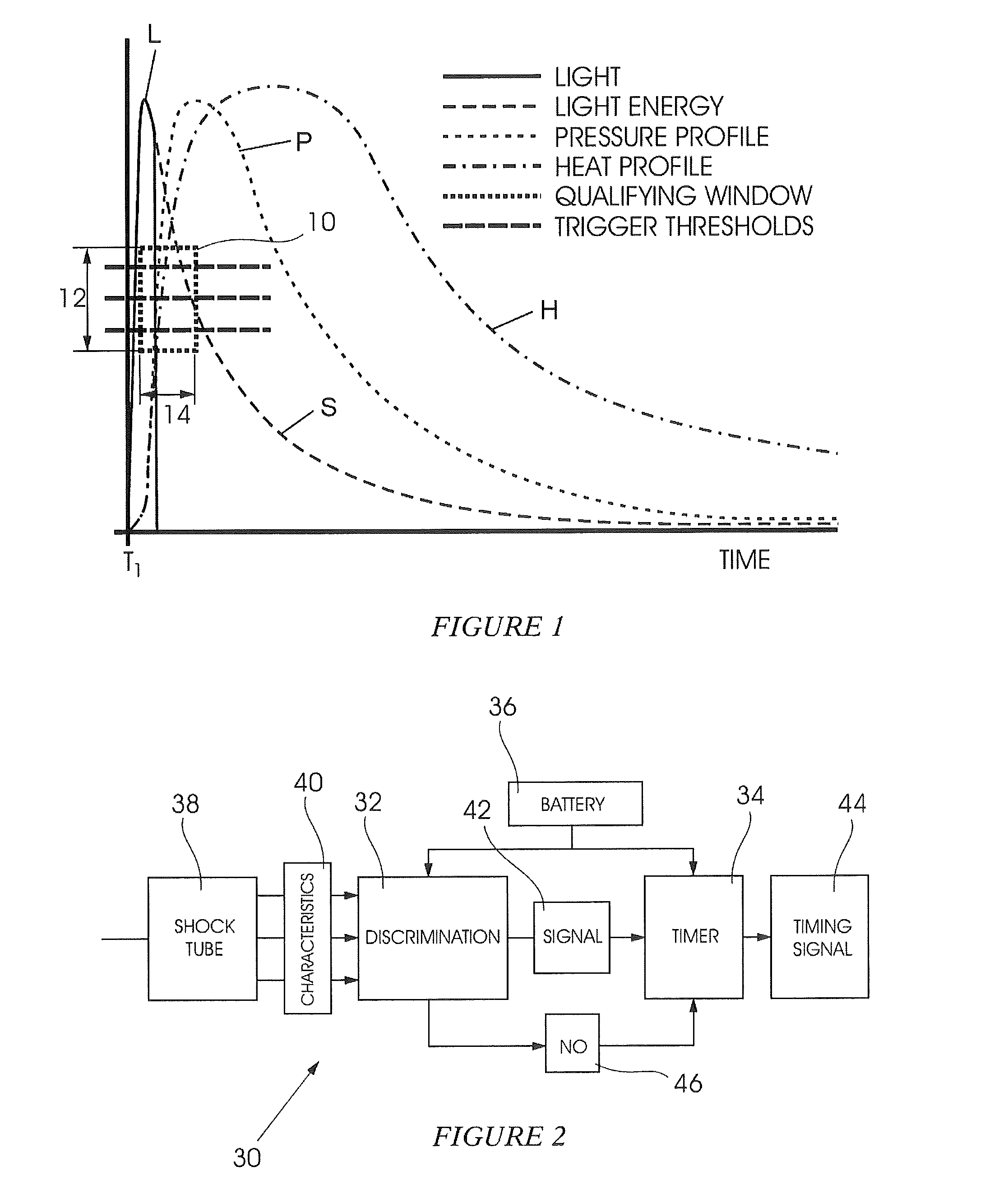
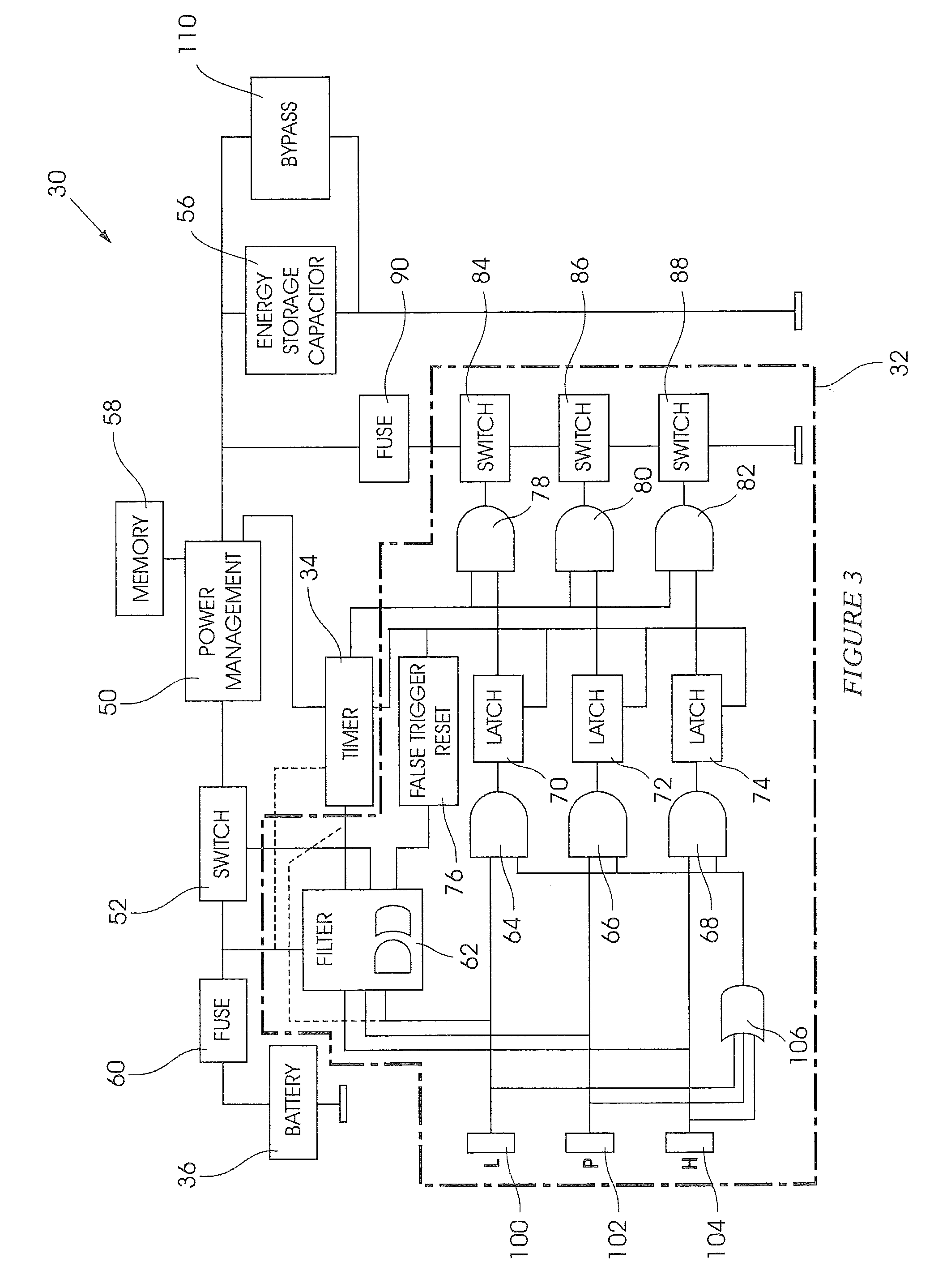
The module effectively eliminates the need for electrical conductors by validating shock tube event parameters, ensuring reliable and accurate time delays, and preventing incorrect detonator firing through a multi-sensor validation process.

Problems solved by technology

The cost of the conductors, which are normally of copper, can be high and constitutes a significant part of the overall cost of the system.
These techniques have, however, not been adopted on a large scale.
Also, the time delay can extend over a lengthy period, several seconds in duration.
The accuracy is dependent on chemical and physical events and, inherently, it is usually not possible to generate a time delay period of several seconds duration with the same degree of accuracy as with an electronic timing module.
However, some implementations are relatively expensive.
Detection of light in the second tube could thus be linked, erroneously, to a shock tube event in the second shock tube and this could result in incorrect operation of a detonator system.

Method used


Image

  • Timing module
  • Timing module
  • Timing module

Examples


Embodiment Construction

[0052]The propagation of a signal by a shock tube, whether by means of a combustion, deflagration, detonation or similar process (referred to herein as a “shock tube event”), produces a number of distinct physical effects (herein “parameters”) such as the emission of light, the generation of a pressure wave, and the release of heat. The nature of these parameters, their relative amplitudes, and their interrelationship over time, are determined by the physical composition of the shock tube. It is practically impossible to simulate the specific characters and relationships of the parameters which occur in a shock tube event. The invention is based on the realisation that the unique characteristics of the various parameters which are generated by a shock tube event can be used, subject to carefully controlled validation processes, to control the operation of a timer module, and hence of an electronic detonator, in an effective and safe manner.

[0053]FIG. 1 of the accompanying drawings h...


PUM


Abstract

A timing module for use in a detonating system which includes discriminating and validating arrangements which sense and validate at least one characteristic of at least one parameter produced by at least one shock tube event and an electronic timer which executes a timing interval in response thereto.

Description

CROSS-REFERENCE TO RELATED APPLICATION[0001]This application claims priority to South African Provisional Patent Application No. 2010 / 04911, filed Jul. 12, 2010, incorporated by reference herein in its entirety.BACKGROUND OF THE INVENTION[0002]1. Field of the Invention[0003]This invention relates to a timing module for use in a blasting system.[0004]2. Related Art[0005]Electronic detonators in a blasting system are typically interconnected through the use of elongate electrical conductors. The cost of the conductors, which are normally of copper, can be high and constitutes a significant part of the overall cost of the system.[0006]Alternative approaches have been used to establish blasting systems. For example, detonators can be interconnected by using fibre optic cables. It is also possible to fire detonators, which are not physically interconnected, by using radio frequency signals. These techniques have, however, not been adopted on a large scale.[0007]An electronic timing modul...

Claims


Application Information

Patent Timeline
Patent Type & Authority Patents(United States)
IPC IPC(8): F42D1/05F42B3/12F42C11/06F42D1/04G04F10/00
CPCF42D1/043F42B3/121F42C11/06G04F10/00F42D1/042F42D1/05
Inventor HARDING, DAVID BRUCELABUSCHAGNE, ALBERTUS ABRAHAMKOEKEMOER, ANDRE LOUISBIRKIN, CHRISTOPHER MALCOLMSCHLENTER, CRAIG CHARLES
Owner DETNET SOUTH AFRICA (PTY) LTD
Learn More