Bypass valve

a bypass valve and valve body technology, applied in the field of medical instruments, can solve the problems of insufficient use precision, waste of resources, and insufficient concentration of outputted anesthetic gas, and achieve the effect of good gas tightness and good structur

Inactive Publication Date: 2015-03-03
BEIJING AEONMED
View PDF18 Cites 0 Cited by
  • Summary
  • Abstract
  • Description
  • Claims
  • Application Information

AI Technical Summary

Benefits of technology

[0006]An object of the present invention is to solve the problem of a gas backflow phenomenon caused by the pressure fluctuation at the gas outlet of the traditional bypass valve, which further causes the imprecise concentration of the outputted anesthetic gas. Therefore, the present invention provides a bypass valve, in which a check valve is introduced at the gas outlet of the bypass valve, to allow the gas to flow unidirectionally without causing the gas backflow phenomenon, and the inventive bypass valve has advantages of a good structure and good gas tightness.
[0011]Preferably, inner threads are arranged in an upper part of the first cavity, and the valve cover is provided with external threads matching with the inner threads, such that the valve cover is threadedly connected to the valve body; two grooves are circumferentially arranged on the valve cover at an upper side and a lower side of the external threads respectively and each are used for accommodating the sealing rings; the sealing ring located at the upper side of the external threads is used for enhancing the gas tightness between the valve cover and the evaporator, while the other one located at the lower side of the external threads is used for enhancing the gas tightness between the valve cover and the valve body of the bypass valve;
[0023]The beneficial effects of the present invention are described below. A check valve is arranged at the gas outlet of the valve body, and the check valve is opened when the gas flows in a normal direction and then smoothly flows out; when a pressure fluctuation at the gas outlet results in a gas reverse backflow, the check valve is closed to prevent the gas backflow, such that the concentration of the outputted anesthetic gas is accurate, reliable, and consistent with a preset value. Specifically, the check valve includes a check valve body and a ventilation plate, both of which achieve the open or close of the check valve by coordinating with the first sealing gasket. When the gas flows in the normal direction, i.e. from the first cavity to the gas outlet, the sealing gasket is pushed to move towards the first gas passage under the action of the gas pressure, such that a gap is present between the first sealing gasket and the ventilation plate, and the gas flows from ventilation holes towards the first gas passage, and then is outputted; and when the gas flows in a reverse direction, i.e. the gas flows inwardly from the first gas passage, the first sealing gasket is attached to the ventilation plate under the action of the gas pressure, such that the communication between the first gas passage and the gas outlet is blocked, and the gas cannot flow into the bypass valve from the first gas passage. With two sealing rings arranged at the connection joint between the valve cover and the valve body, the gas tightness between the valve cover and the valve body or an evaporator is enhanced. Sealing rings are arranged at the connection joints between the valve body and the check valve body as well as the ventilation plate, which enhances the gas tightness between the check valve and the valve body. Compared to prior art, the inventive bypass valve has advantages of ensuring a unidirectional gas flow, a simple structure and better gas tightness.

Problems solved by technology

Poor gas tightness of the bypass valve may cause the leakage of a part of the gas, thus resulting in a waste of resources.
Poor gas tightness of the bypass valve may cause the leakage of the anesthetic, causing not only a waste of resources, but also an anesthesia to doctors, which has a great impact on the surgery quality and patient safety.
In practice, a gas backflow occurs to the bypass valve in the case of pressure fluctuation at the gas outlet, resulting in a concentration of the outputted anesthetic gas that is not precise enough to be used conveniently; meanwhile, the traditional bypass valve has still defects such as a structural and technological defect, poor gas tightness, and so on.

Method used


Image

  • Bypass valve
  • Bypass valve
  • Bypass valve

Examples


Embodiment Construction

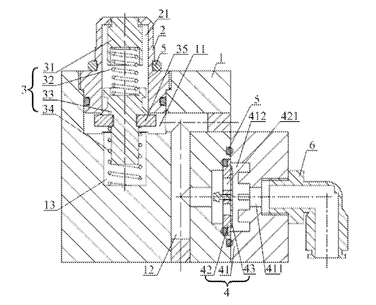
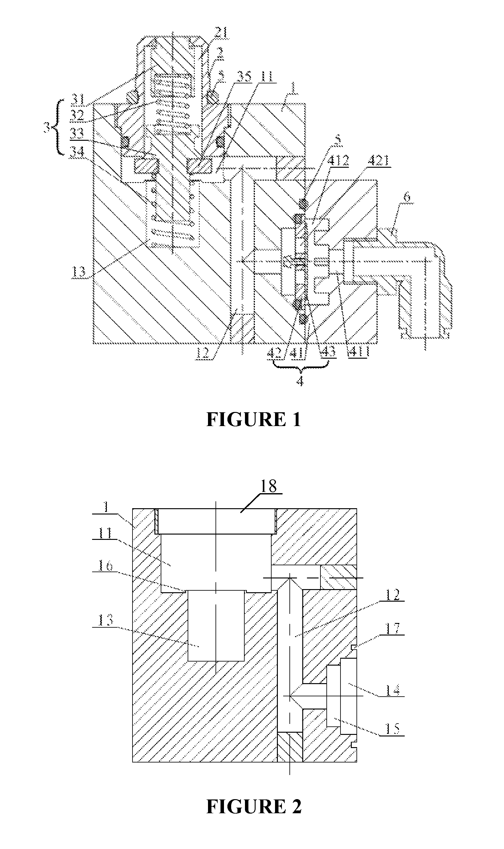
[0055]As shown in FIG. 1, in an embodiment, a bypass valve according to the present invention includes a valve body 1, which includes a gas inlet 18 and a gas outlet. A check valve 4 including a check valve body 41, a ventilation plate 42 and a first sealing gasket 43 is arranged at the gas outlet. A first gas passage 411 for transmitting the gas is arranged within the check valve body 41, the ventilation plate 42 is provided with ventilation holes 421 in communication with the gas outlet, and the first sealing gasket 43 is arranged between the ventilation plate 42 and the check valve body 41, so that the first gas passage 411 is selectively communicated with the ventilation holes 421 by the first sealing gasket 43. When the gas flows out from the gas outlet, the check valve 4 is opened in that a gap is present between the first sealing gasket 43 and the ventilation plate 42, such that the ventilation holes 421 are in communication with the first gas passage 411, and hence the gas c...


PUM


Abstract

Disclosed is a bypass valve comprising a valve body. The valve body has a gas inlet and a gas outlet, wherein a check valve is provided at the air outlet. The check valve comprises a check valve body, a ventilation plate and a first sealing gasket. A first gas passage for gas delivering is provided within the check valve body; ventilation holes are provided on the ventilation plate; the ventilation holes are in communication with the gas outlet; the first sealing gasket is provided between the ventilation plate and the check valve body; and the first gas passage and the ventilation holes are in selective communication with each other via the first sealing gasket. The uni-directional check valve is provided in the gas air outlet in the bypass valve, causing the direction of the gas flow to be unique, overcoming the problem of imprecise concentration of the anaesthetic gas caused by the a gas backflow, and having the advantage of structural technology and better gas tightness.

Description

TECHNICAL FIELD[0001]The present invention relates to the field of medical instruments, in particular to a bypass valve.TECHNICAL BACKGROUND[0002]An anesthesia machine, which is an equipment very demanding for security, stability and operability used in the operating room, is applicable to deliver an anesthetic into pulmonary alveoli of a patient via a mechanical circuit and form a partial pressure of anesthetic gas in the pulmonary alveoli. The anesthetic has a direct inhibition action on the central nervous system after being diffused into blood, resulting in an effect of general anesthesia. The anesthesia machine preliminarily includes four parts of a gas supply system, a vaporizer, a ventilator and a circuit system.[0003]The anesthetic evaporator, as a vital component in the anesthesia machine, is introduced to the anesthesia machine to provide the patient with a stable anesthetic gas mixture of an accurate concentration. The anesthetic evaporator can effectively evaporate the a...

Claims


Application Information

Patent Timeline
Patent Type & Authority Patents(United States)
IPC IPC(8): F16K15/00A61M16/18A61M16/20F16K15/14
CPCA61M16/183F16K15/148A61M16/20A61M16/208Y10T137/7859Y10T137/789Y10T137/88046Y10T137/88054
Inventor ZHENG, DIANHUI
Owner BEIJING AEONMED
Why Eureka
Try Eureka