
Method and system for disconnecting a generator from a power system

a technology of power system and generator, applied in emergency protective circuit arrangements, relays, transportation and packaging, etc., can solve the problems of generator loss of torque, generator being subject to severe conditions, electrical and mechanical stress to the generator, etc., and achieve the effect of less stress

Active Publication Date: 2015-03-03
HITACHI ENERGY LTD
View PDF22 Cites 0 Cited by
  • Summary
  • Abstract
  • Description
  • Claims
  • Application Information

AI Technical Summary

Benefits of technology

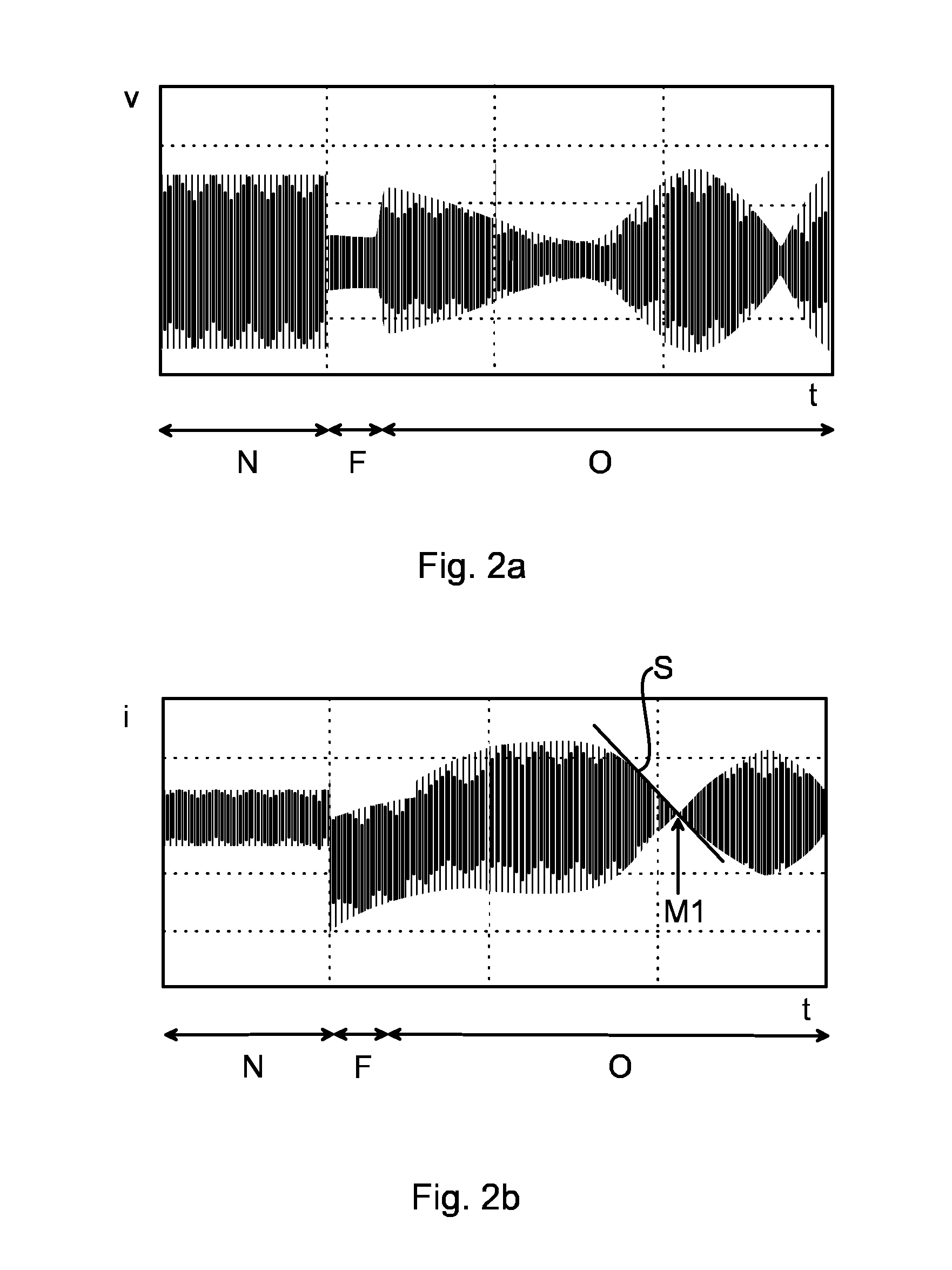
This approach minimizes electrical and mechanical stress on the generator and circuit breakers by disconnecting at the parameter's minimum amplitude, ensuring minimal impact on the generator and reducing the deviation in the electrical parameter's magnitude.

Problems solved by technology

Generators, which may provide electrical power in a power system, are normally sensitive to disturbances in the operating conditions of the power system to which they are connected.
During an out-of-step condition, high peak currents, off-frequency operation, and pulsating torques due to the rotor angle varying between 0 and 2π radians may cause electrical and mechanical stress to the generator.
As a result, the generator loses torque.
The generator is hence subject to severe conditions until the circuit breakers disconnect the generator from the power system.
A drawback with the current solution is that the circuit breakers as well as the generator are exposed to high stress prior to disconnecting the generator from the power system.

Method used


Image

  • Method and system for disconnecting a generator from a power system
  • Method and system for disconnecting a generator from a power system
  • Method and system for disconnecting a generator from a power system

Examples


Embodiment Construction

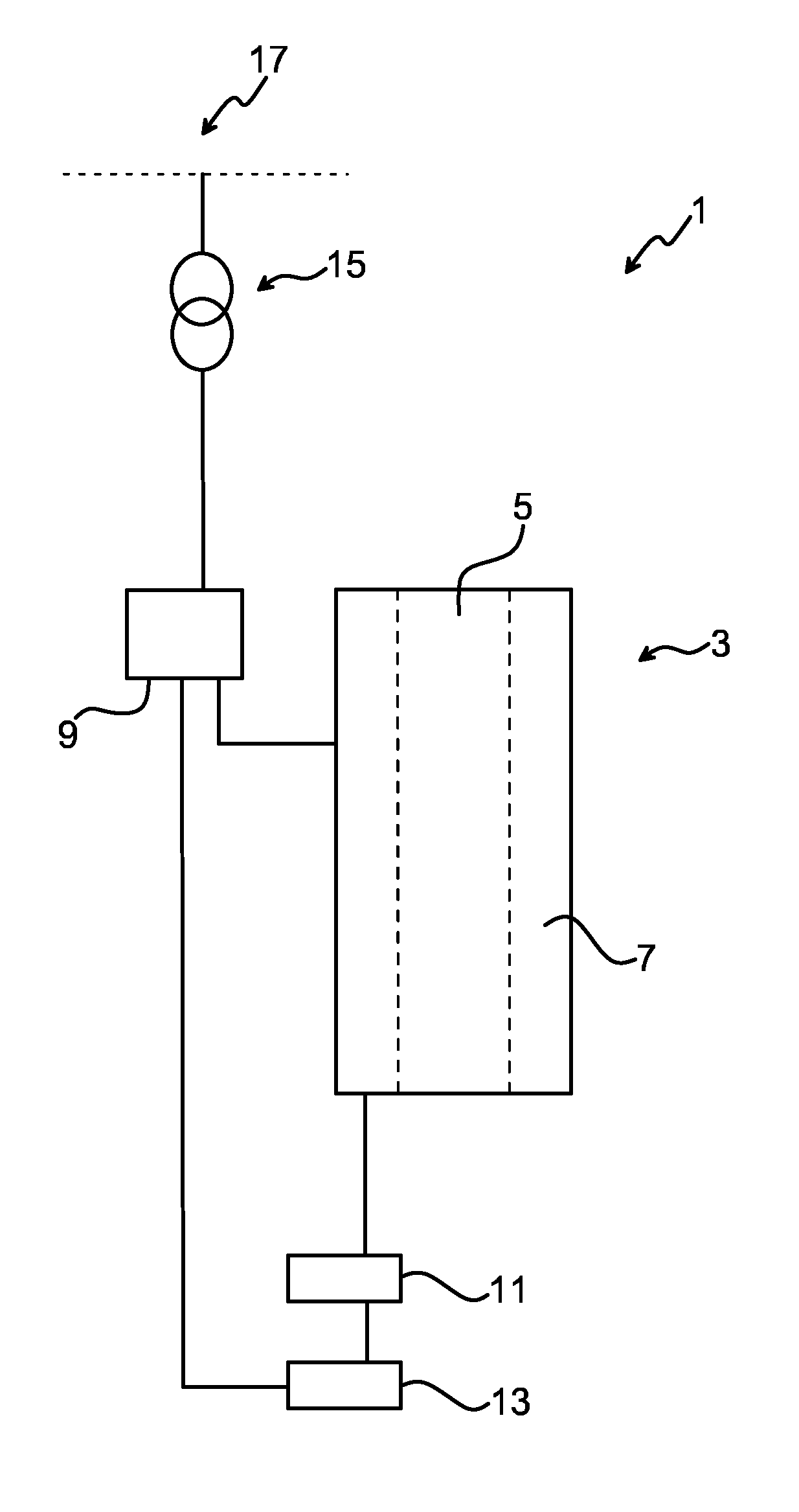
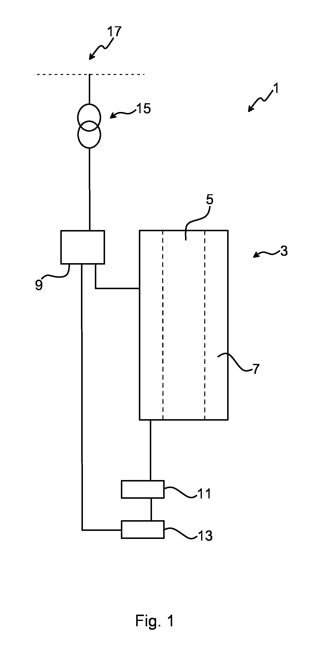
[0035]FIG. 1 illustrates a protection system 1 for a generator 3. The system 1 comprises the generator 3, a plurality of circuit breakers 9, a measuring unit 11 and a processing unit 13. The measuring unit and the processing unit may in one embodiment be integrated into one unit (not shown). The generator 3 is typically a synchronous generator.

[0036]The generator 3 comprises a rotor 5 and a stator 7. The rotor 5 is illustrated schematically in FIG. 1 with dashed lines inside the stator 7. The rotor 5 typically has rotor windings to electrically magnetize the rotor. Alternatively, the rotor 5 may comprise a permanent magnet.

[0037]The stator 7 has stator windings, which are not shown in FIG. 1. The rotor windings and stator windings interact as the rotor rotates. Typically, a rectified alternating current or a dc current is applied to the rotor windings so as to induce a magnetic field in the rotor windings and magnetize the rotor 5. Thereby, a magnetic field and stator currents will ...


PUM


Abstract

A method for disconnecting a generator from a power system when the generator and the thereto connected power system are non-synchronized. The method includes the steps of: determining that there is a loss of synchronization between the generator and the power system, which loss of synchronization provides an amplitude variation of an electrical parameter associated with the generator. The method further includes determining when a minimum amplitude of the electrical parameter will occur, wherein when the occurrence of the minimum amplitude has been predicted, providing a command signal for disconnecting the generator from the power system, wherein the command signal is provided prior to the minimum amplitude of the electrical parameter is attained, and disconnecting the generator from the power system approximately when the determined minimum amplitude of the electrical parameter occurs. It is also presented a protection system for a generator in a power system.

Description

FIELD OF THE INVENTION[0001]The invention generally relates to protection of electrical equipment in a power system and in particular to disconnecting a generator from a power system when the generator and the power system fall out of synchronization.BACKGROUND OF THE INVENTION[0002]Generators, which may provide electrical power in a power system, are normally sensitive to disturbances in the operating conditions of the power system to which they are connected.[0003]A disturbance or a fault condition in the power system may give rise to an out-of-step condition, i.e. the loss of synchronization between different areas within a power system, or alternatively loss of synchronization between e.g. two interconnected power systems.[0004]During an out-of-step condition, high peak currents, off-frequency operation, and pulsating torques due to the rotor angle varying between 0 and 2π radians may cause electrical and mechanical stress to the generator. By rotor angle is meant the angle betw...

Claims


Application Information

Patent Timeline
Patent Type & Authority Patents(United States)
IPC IPC(8): H01H47/00H02H3/02H02H3/48H02H7/06H02J3/38
CPCH02H3/021H02H3/48H02H7/06H02J3/38H02J2003/388H02J3/388
Inventor BRNCIC, IVOFORSMAN, SOREN
Owner HITACHI ENERGY LTD
Learn More