Tracking objects in conduits

a technology of conduits and objects, applied in the direction of instruments, specific gravity measurement, wave/particle radiation conversion of sensor output, etc., can solve the problems of difficult effective and efficient monitoring, huge economic loss, environmental impact and potentially catastrophic physical damage,

Active Publication Date: 2015-03-10
OPTASENSE HLDG LTD
View PDF28 Cites 24 Cited by
  • Summary
  • Abstract
  • Description
  • Claims
  • Application Information

AI Technical Summary

Benefits of technology

[0044]Whilst the movement of an object such as a pig within a conduit may provide a sufficient pressure pulse for conduit condition monitoring the conduit may be also be provided with an impulse for generating additional pressure pulses when there is no pig moving within a section of pipeline. The impulser may be anything capable of exciting pressure pulses within the conduit. Providing an impulse allows conduit condition monitoring in periods when no p

Problems solved by technology

The continuing proper operation of these pipelines is of paramount importance, and failures carry massive economic loss, environmental impact and potentially catastrophic physical damage also.
The sheer size of many pipeline networks however, and the fact that many kilometres of pipelines consist of underground or sub-sea installations makes effective and efficient monitoring a difficult problem.
An intelligent monitoring pig may be comprise various sensors and an onboard processor and can be a very expensive, very complex instrument.
However, occasionally pigs may become stuck in a pipeline.
An area of excessive residue build up may present too much of an obstacle to a pig.
Also, in normal operation the debris from the cleaning action builds up in front of the pig and in some instances can block passage of the pig.
Damage to the pipeline, such as denting or buckling, may also cause a change in the in

Method used


Image

  • Tracking objects in conduits
  • Tracking objects in conduits
  • Tracking objects in conduits

Examples


Embodiment Construction

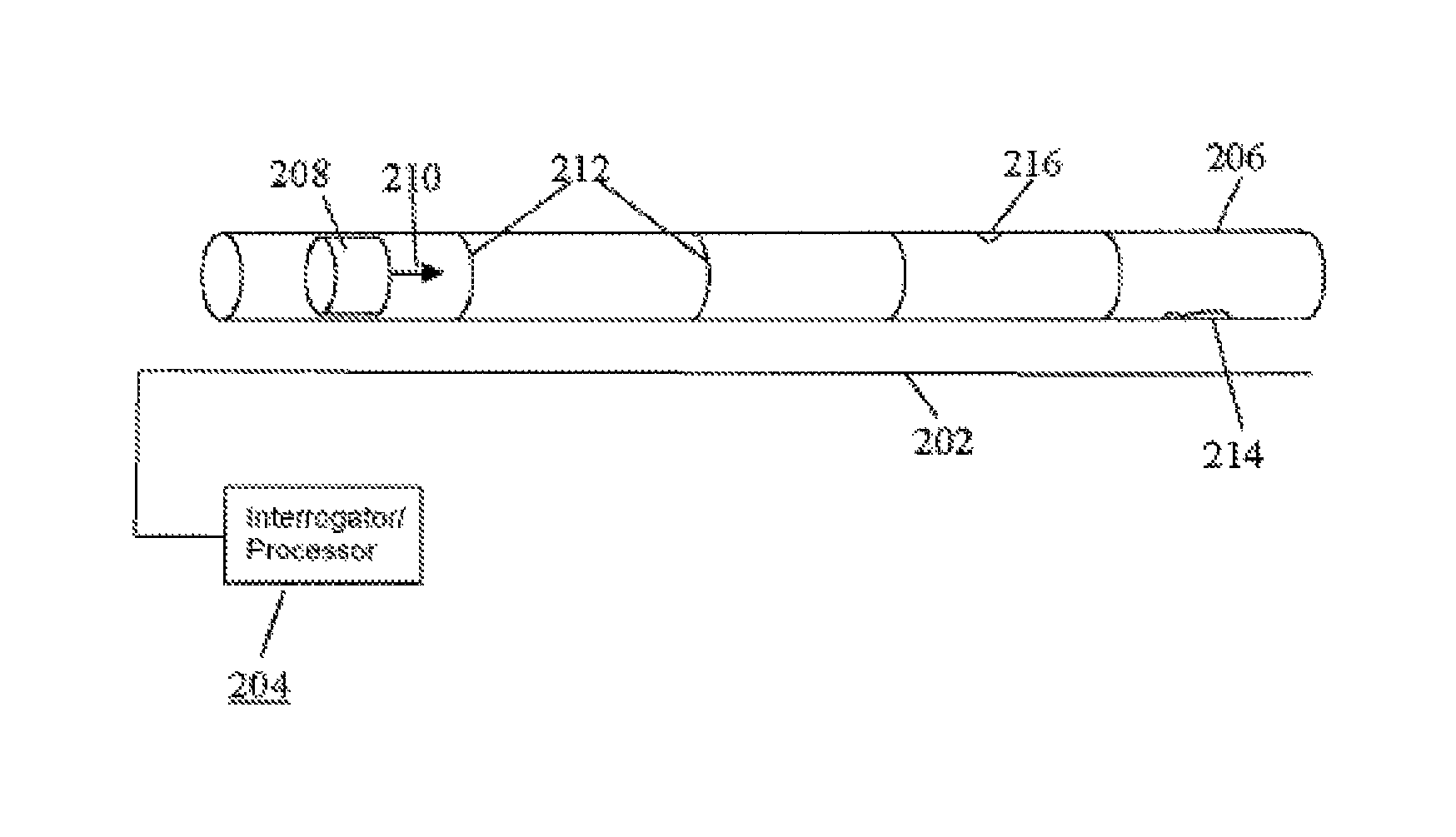
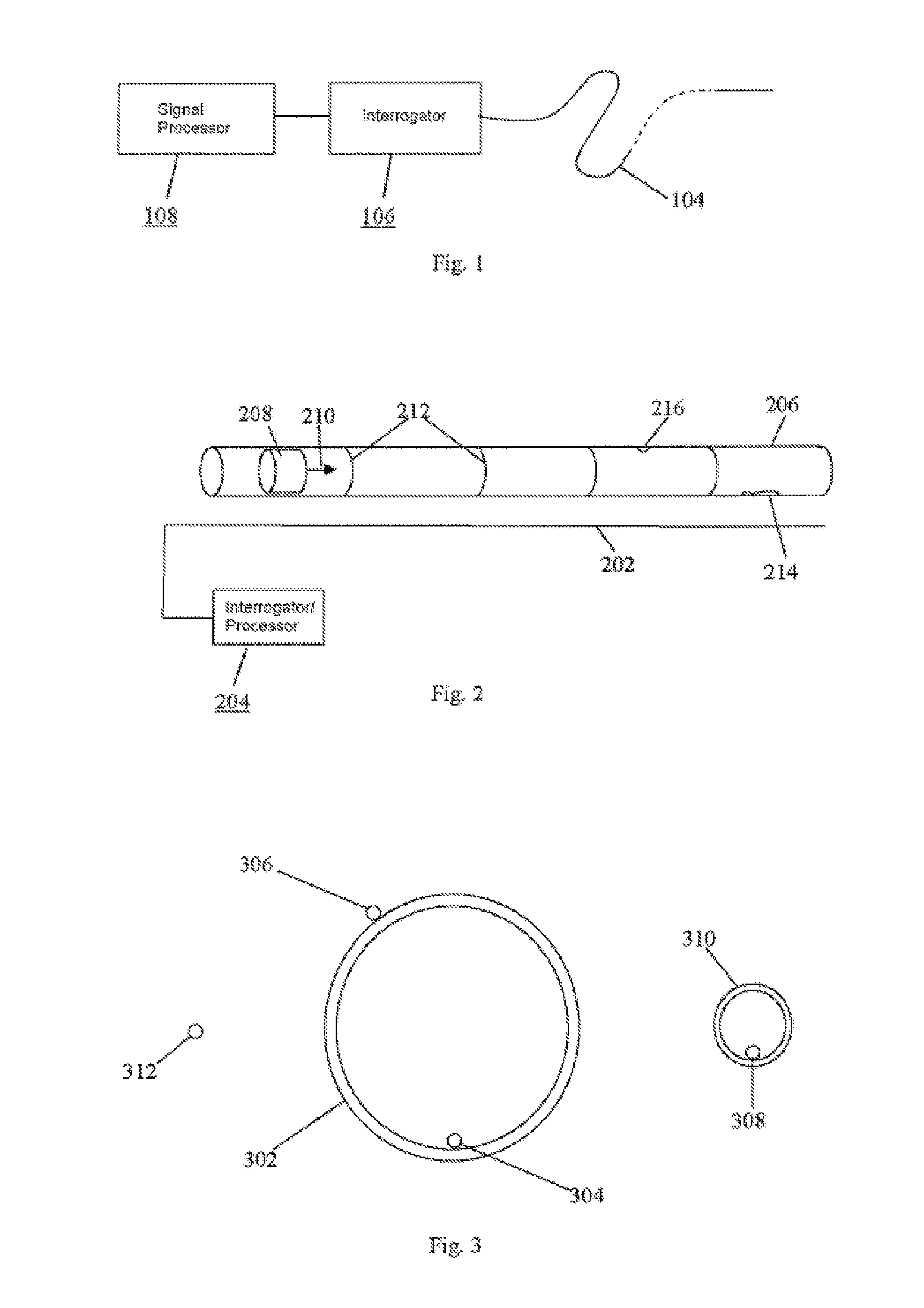
[0062]FIG. 1 shows a schematic of a distributed fibre optic sensing arrangement. A length of sensing fibre 104, which may be standard optic fibre such as used in telecommunication applications, is connected at one end to an interrogator 106. The output from interrogator 106 is passed to a signal processor 108 and optionally a user interface, which in practice may be realised by an appropriately specified PC. The sensing fibre can be many kilometres in length, and in this example is approximately 40 km long.

[0063]The interrogator launches an interrogating optical signal, which may for example comprise a series of pulses having a selected frequency pattern, into the sensing fibre. The phenomenon of Rayleigh backscattering results in some fraction of the light input into the fibre being reflected back to the interrogator, where it is detected to provide an output signal which is representative of acoustic disturbances in the vicinity of the fibre. The form of the optical input and the ...


PUM


Abstract

Methods and apparatus for tracking objects in conduits, especially for tracking the movement of a pig in a pipeline, are disclosed. Distributed acoustic sensing is used to obtain signal returns from a plurality of discrete longitudinal sensing portions of a fibre optic cable which is laid along the length of the conduit. The method involves detecting an acoustic signature corresponding to the object moving in the conduit. The acoustic signature may comprise a series of pressure pulses caused by the object traversing joints etc. in the conduit. Preferably the method involves detecting pressure waves caused by the object as it moves through the conduit. Detecting the characteristic pressure wave signal provides discrimination of the object from other acoustic disturbances. In pipeline applications a pig can be tracked in real time, if the pig stops moving an alert can be generated and the location of the pig will be known.

Description

FIELD OF THE INVENTION[0001]The present invention relates to tracking objects in conduits, and more particularly to tracking objects such as cleaning or inspection apparatus, e.g. pigs, in pipelines.BACKGROUND OF THE INVENTION[0002]Pipelines are the most economically viable method of transporting fluid assets, most commonly oil and gas, but other types of pipeline also exist. A vast pipeline infrastructure exists today responsible for gathering, transporting and distributing these natural resources, with over three quarters of a million kilometers of oil and gas pipelines in the US alone. The continuing proper operation of these pipelines is of paramount importance, and failures carry massive economic loss, environmental impact and potentially catastrophic physical damage also.[0003]Significant efforts are therefore made to maintain, monitor and inspect pipelines. The sheer size of many pipeline networks however, and the fact that many kilometres of pipelines consist of underground ...

Claims


Application Information

Patent Timeline
IPC IPC(8): G01H9/00G01D5/26G01M3/24F17D5/06G01D5/48G01P3/14
CPCG01M3/243F17D5/06G01D5/48G01H9/004G01P3/14G01M3/047
Inventor HILL, DAVID JOHNMCEWEN-KING, MAGNUS
Owner OPTASENSE HLDG LTD
Why Eureka
Try Eureka