Protective shell for a hand held plasma cutting torch

a protection shell and plasma cutting technology, which is applied in the direction of plasma welding apparatus, manufacturing tools, solventing apparatus, etc., can solve the problems of high melting temperature, plastic can become embrittled, and susceptible to cracking, so as to enhance the robustness, improve the visual image of the torch, and improve the effect of molten spatter resistan

Active Publication Date: 2015-03-10
HYPERTHERM INC
View PDF18 Cites 2 Cited by
  • Summary
  • Abstract
  • Description
  • Claims
  • Application Information

AI Technical Summary

Benefits of technology

[0005]What is needed is an electrically insulating shell for providing a plasma torch head with more robustness against molten spatter, dropping impact, UV light, and heat. An insulating shell covering the torch head and / or handle can enhance the robustness and improve the visual image of the torch.

Problems solved by technology

However, plasma cutting torches are intended to cut metal, which inherently has a higher melting temperature than the plastic housings of plasma arc torches.
In addition, the plastic can become embrittled and susceptible to cracking with repeated impact events (for example, if the torch is accidently dropped or improperly used as a hammer).

Method used


Image

  • Protective shell for a hand held plasma cutting torch
  • Protective shell for a hand held plasma cutting torch
  • Protective shell for a hand held plasma cutting torch

Examples


Embodiment Construction

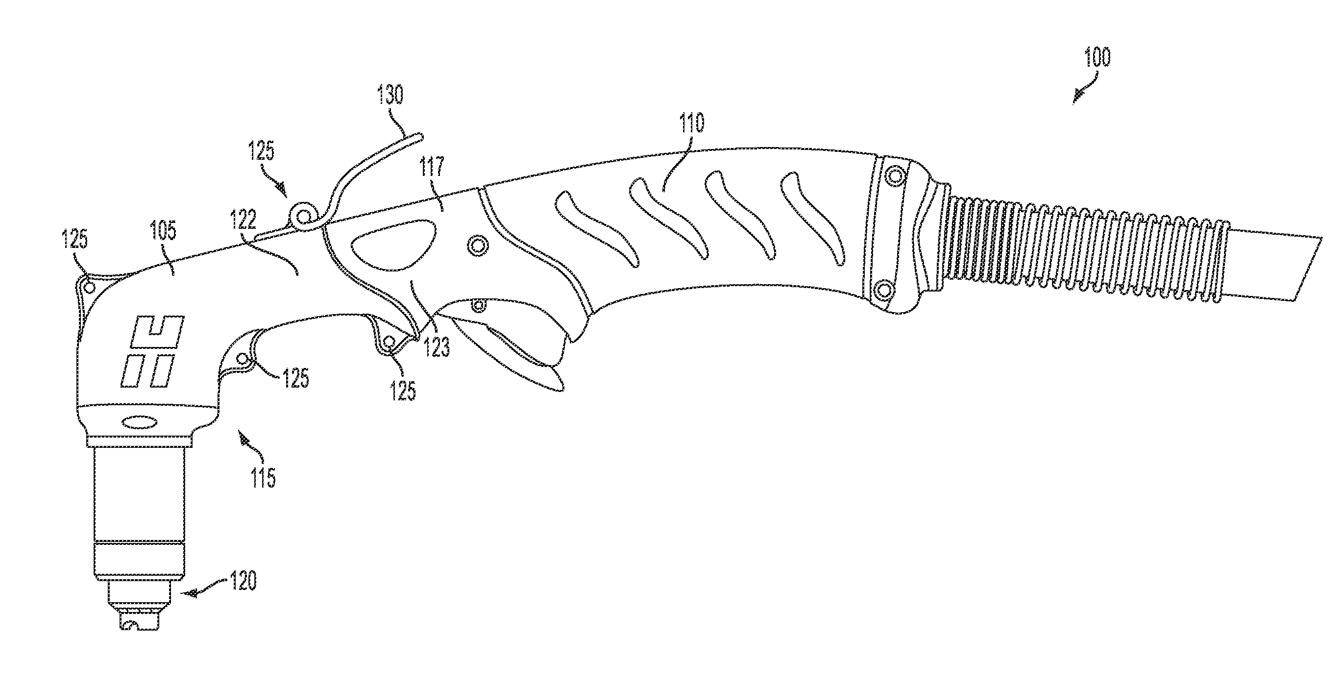
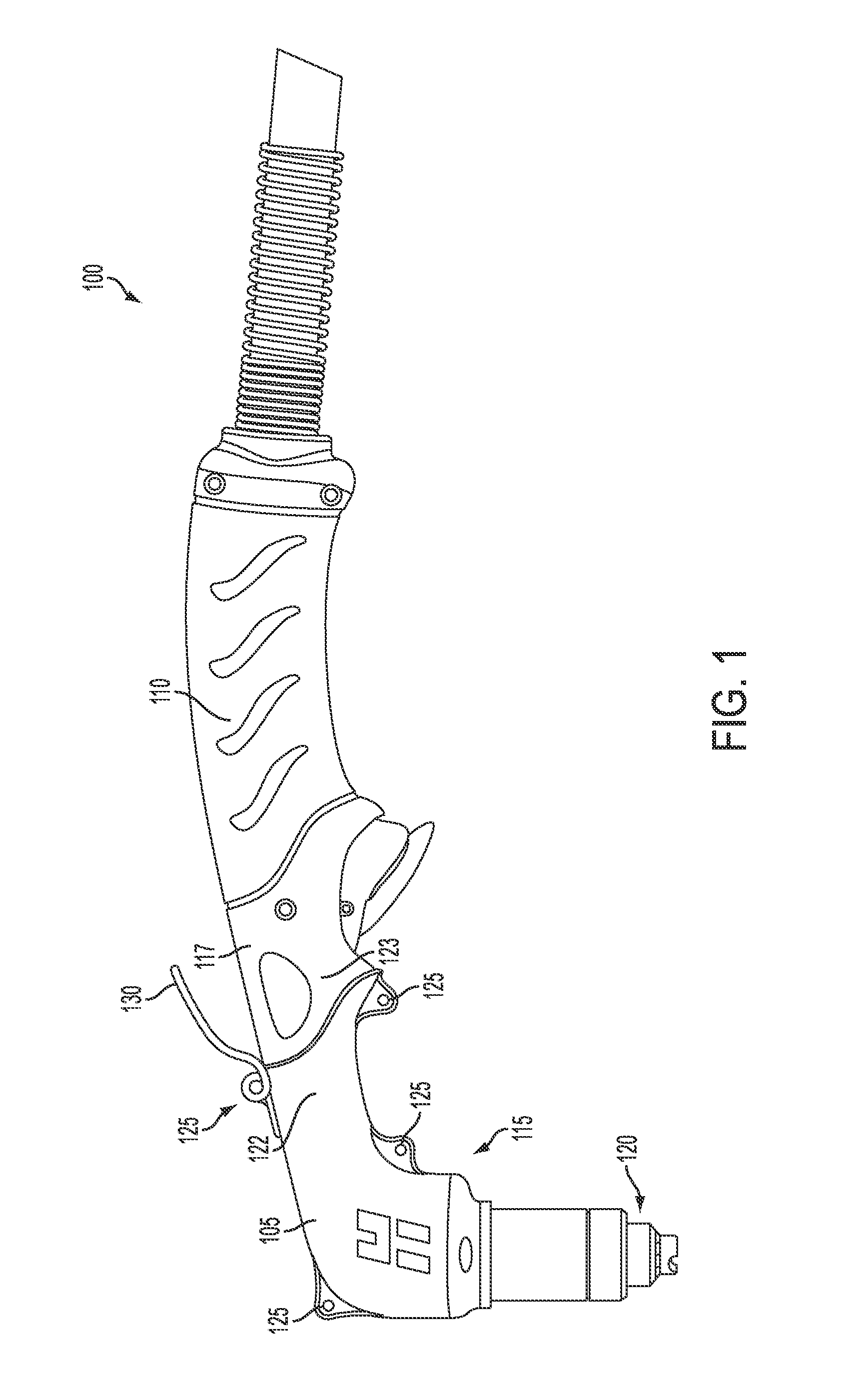
[0017]FIG. 1 shows a plasma arc torch 100 having a protective shell 105. The plasma arc torch 100 includes a handle 110, a head 115, a torch body 117, and a torch tip 120. The head 115 extends from the handle 110 and the torch tip 120 extends from the head 115. The plasma torch tip 120 can include a variety of different consumables including, for example, an electrode, nozzle, retaining cap, shield and / or swirl ring. The torch 100 and torch tip 120 can include electrical connections, passages for cooling, and passages for arc control fluids (e.g., plasma gas).

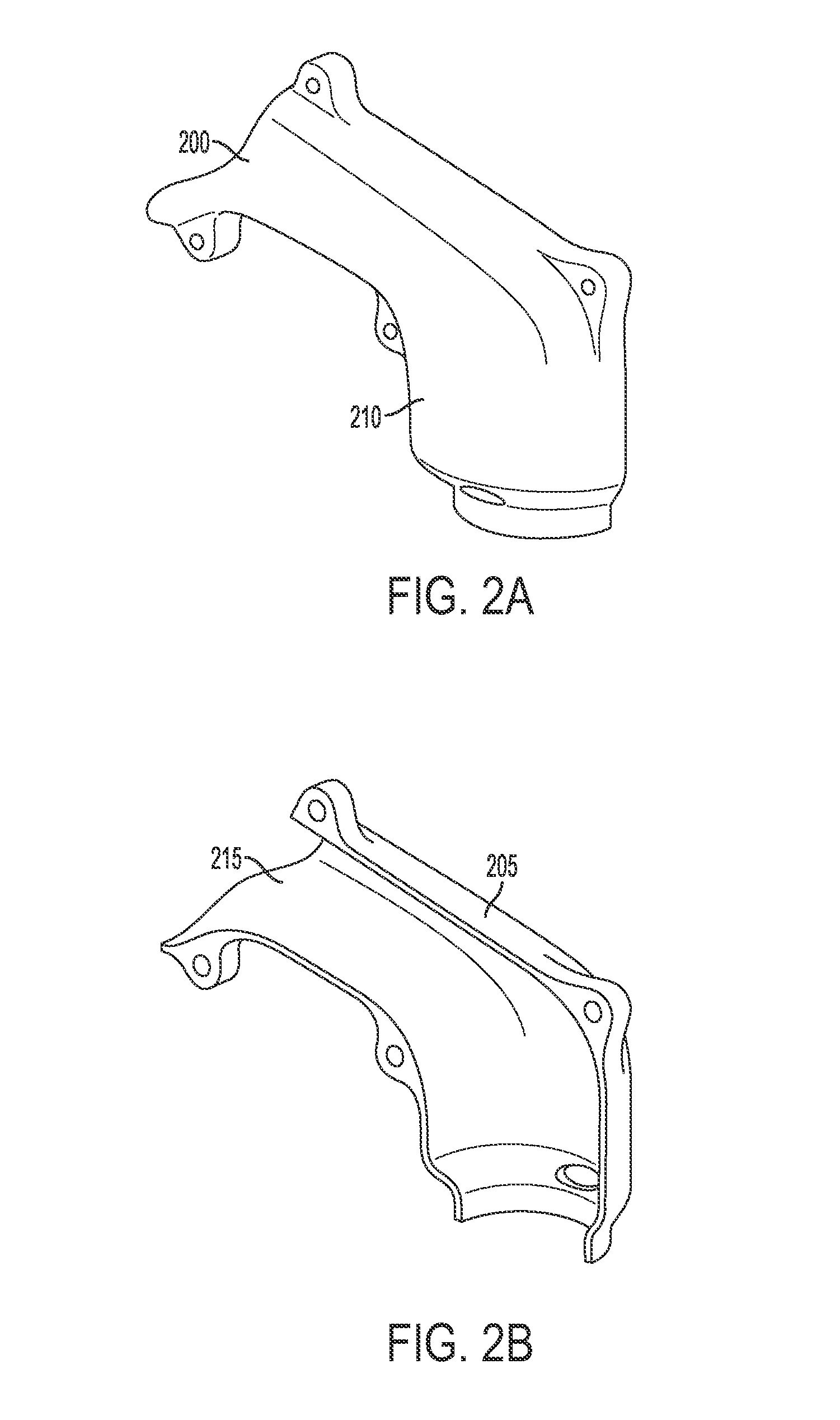
[0018]The protective shell 105 can be formed from two separate shell sections, for example, a first shell section 122 and a second shell section (not shown in FIG. 1, but see, e.g., the shell sections 200 and 205 of FIGS. 2A and 2B) located opposite to the first shell section. The first and second shell sections 122 can be structurally independent from an outer surface of the plasma torch body 117 (e.g., when first and second s...


PUM

PropertyMeasurementUnit
voltageaaaaaaaaaa
voltageaaaaaaaaaa
voltageaaaaaaaaaa

Abstract

A protective shell for surrounding a portion of a body of a handheld plasma torch includes a first and second shell section. The plasma torch body includes a handle, a head extending from the handle and a torch tip extending from the head. The first shell section is structurally independent from an outer surface of the plasma torch body. The second shell section is structurally independent from the outer surface of the plasma torch body and is capable of being secured to the first shell section such that, in combination, the first and second shell sections surround the torch head and provide (i) structural protection to the torch head and (ii) thermal insulation to the torch head, wherein the first and second shell sections are electrically insulated relative to the torch head.

Description

RELATED APPLICATIONS[0001]This application claims the benefit of and priority to U.S. Provisional Application No. 61 / 365,088, filed Jul. 16, 2010, the entirety of which is hereby incorporated herein by reference.TECHNICAL FIELD[0002]The present invention relates generally to plasma arc cutting torches, and more particularly, to a heat shield for a hand held plasma cutting torch.BACKGROUND[0003]Welding and plasma arc torches are widely used in the welding, cutting, and marking of materials. A plasma torch generally includes an electrode, and a nozzle having a central exit orifice mounted within a torch body, electrical connections, passages for cooling, passages for arc control fluids (e.g., plasma gas), and a power supply. A swirl ring can be employed to control fluid flow patterns in the plasma chamber formed between the electrode and nozzle. The torch produces a plasma arc, a constricted ionized jet of a gas with high temperature and high momentum. Gases used in the torch can be n...

Claims


Application Information

Patent Timeline
Patent Type & Authority Patents(United States)
IPC IPC(8): B23K10/00B23K9/013B23K10/02H05H1/34
CPCB23K9/013B23K10/00B23K10/02H05H1/34H05H2001/3473H05H1/3473
Inventor ROBERTS, JESSETWAROG, PETER
Owner HYPERTHERM INC
Why Eureka
Try Eureka